SSC377/D, 5M30 64/128MB, 1Tops1. 支持双摄,甚至三摄;2. 夜视全彩;3. 省内存、省带宽;4. 算力较大,适合新的算法模型;
High Performance Processor Core
ARM Cortex-A35
Clock rate up to 1.0 GHz
Neon and FPU
Memory Management Unit for Linux support
DMA Engine
Image/Video Processor
Supports 8/10/12-bit parallel interface for
raw data input
Supports MIPI interface with 2+2 or 4 data
lanes and 2 clock lanes
Supports sensor interface with both parallel
and MIPI
Supports 8-bit CCIR656 interface
Supports max. 3072*1728+D1 pixels video
recording and image snapshot
Fixed Pattern Noise (FPN) reduction
Static and adaptive bad pixel compensation
Crosstalk noise reduction
Temporal-domain Noise Reduction (3DNR)
Sharpening filters for image enhancement
Spatial-domain Noise Reduction (2DNR) for
luma and chroma image
F
ilter to remove purple false color in highlight
regions
Optical black correction
Symmetric/Asymmetric lens shading
compensation
Auto White Balance (AWB) / Auto Exposure
(AE) / Auto Focus (AF)
CFA color interpolation and demoire filter
Color correction and color adjustment engine
Gamma correction
Video stabilization
High Dynamic Range (HDR) with two
exposure frames and de-ghost function
Frame buffer data compression and de-
compression to save memory bandwidth
Wide Dynamic Range (WDR) with local tone
mapping
Flip, Mirror, and Rotation with 90 or 270
degree
Lens Distortion Correction (LDC)
Rolling shutter compensation
Fully programmable multi-function scaling
engines
Advanced Color Engine
Luma gain/offset adjustment
Supports 2D peaking with user definition
filter
Horizontal noise masking
Local Contrast Enhancement (LCE)
Direct Luma Correction (DLC)
Black/White Level Extension (BLE/WLE)
IHC/ICC/IBC for hue, saturation, brightness
and favorite color adjustment
Histogram statistics
H.265/HEVC Encoder
Fully compatible with ISO/IEC 23008-2 High
Efficiency video coding
Main Profile, Level 5.0 encode
Supports I-frame and P-frame
1/4-pixel precision motion vectors
Deblocking filter and Sample Adaptive Offset
(SAO)
Picture/CTU/subCTU level rate control
Region of Interest (ROI) encoding with
custom QP map
H.264/AVC Encoder
Compatible with the ITU-T Recommendation
H.264 specification
Baseline/Constrained Baseline/Main/High
Profile, Level 5.1 encode
1/4-pixel precision motion vectors
In-loop deblocking filter
CABAC/CAVLC support
Error resilience tools
Frame level and MB level rate control
Region of Interest (ROI) encoding with
custom QP map
JPEG Encoder
Supports JPEG baseline encoding
Supports YUV422 or YUV420 input formats
Supports max. 3840x3840 resolution
Supports real-time mode and frame encode
mode
Video Encoding Performance
Supports 5M 30 fps H.265/HEVC encoding
Supports 5M 30 fps H.264 encoding
Supports MJPEG up to 5M 30 fps encoding
Intelligence Processing Unit (IPU)
Pure hardwired accelerator
Supports various video analysis functions like
FD/FR, human detection, MD/OD, object
tracking, etc.
Supports FP32 FFT/IFFT for Audio
Supports median filter for TOF
Supports 2D TOF filter
Intelligent Video Engine (IVE)
Supports 30 functions (CSC/Filter/Erode/
Dilate/SAD/3x3/DOT, etc.) for video analysis
Max. resolution 1920x1080
Read/Write DMA
Audio Processor
One stereo ADC for microphone input
Supports 6-channel DMIC (1 clock + 3 data)
One single-end lineout
I2S digital audio input and output with 2-ch
input and 2-ch output
Supports 8KHz/16KHz/32KHz/48KHz
sampling rate audio recording
Digital and analog gain adjustment
NOR/NAND Flash Interface
Compliant with standard, dual and quad SPI
Flash memory components
High speed clock/data rate up to 108MHz
SD Card/eMMC Interface
Compatible with SD spec. 2.0, data bus 1/4
bit mode
Supports eMMC 4.3 interface
SDIO 2.0 Interface
Compatible with SDIO spec. 2.0, data bus
1/4 bit mode
Compatible with SD spec. 2.0, data bus 1/4
bit mode
USB Interface
One USB 2.0 configurable host or device
–
Host mode supports EHCI specification
–
Device mode supports 7 endpoints
DRAM Memory
Embedded 128MB DDR3(L)
Connectivity
Built-in 10/100M Ethernet MAC and Ethernet
PHY
USB 2.0 Host Controller could be used for
USB Wi-Fi Dongle or Module
One SDIO 2.0 Host Controller could be used
for SDIO Wi-Fi module
Security Engines
Supports AES128/AES192/AES256/DES/
3DES/RSA/SHA-I/SHA-256
Supports secure booting
Supports Embedded OTP (One Time
Programmable) memory to store secure and
calibration data
Real Time Clock (RTC)
Built-in RTC working with 32.768 KHz crystal
Alarm interrupt for wakeup
Tick time interrupt (millisecond)
Supports 1Hz precision tuning
Peripherals
Dedicated GPIOs for system control
Supports max. 11 PWM outputs
Two generic UARTs and one fast UART with
flow control
Three generic timers and one watchdog
timer
Two SPI masters
Three I2C Masters
One IR input
Built-in SAR ADC with 2-channel analog
inputs for different kinds of applications
Supports internal temperature sensor
Operating Voltage Range
Core: Typ. 0.9V
I/O: 1.8/3.3V
DRAM: 1.5V (DDR3) or 1.35V (DDR3L)
Power Consumption: TBD
Ambient Temperature: -20°C to +70°C
Package
88-pin QFN, 9mm x 9mm
Moisture Sensitivity Level (MSL): 3
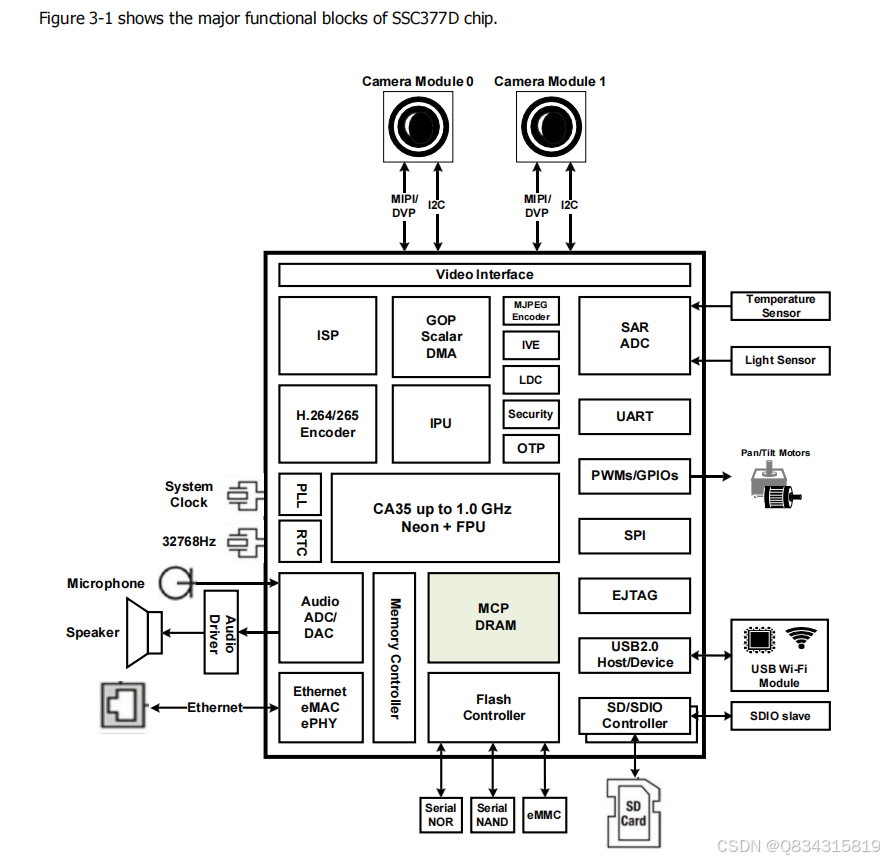
The SSC377D products are highly integrated multimedia System-on-Chip (SoC) products for high-resolution
intelligent video recording applications like IP/Battery camera.
The chip includes ARM Cortex-A35 processor, advanced Image Signal Processor (ISP), high performance
MJPEG/H.264/H.265 video encoder, Intelligence Processing Unit (IPU), Intelligent Video Engine (IVE), as well
as high speed I/O interfaces like MIPI, and Ethernet.
Advanced low-power, low-voltage architecture and optimized design flow are implemented to fulfill long time
usage applications such as handheld and battery devices. Hardwired AES/DES/3DES cipher engines are
integrated to support secure boot, authentication, and video/audio stream encryption in security system.
The SSC377D, powered by SigmaStar Technology, comes with a complete hardware platform and software
SDK, allowing customers to speed up "Time-to-Market."
5.1.
Overview
CPU is based on ARM’s Cortex-A35 family series.
5.2.
Function Description
The CPU has the following features:
Single-core
32K ICACHE / 32K DCACHE
128K L2 CACHE
Up to 1.2GHz, depending on VDD voltage level
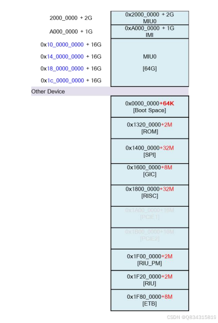
5.3.
Mapping Address
CPU will handle all the sub-system IPs based on the mapping below:
5.1.
Overview
CPU is based on ARM’s Cortex-A35 family series.
5.2.
Function Description
The CPU has the following features:
Single-core
32K ICACHE / 32K DCACHE
128K L2 CACHE
Up to 1.2GHz, depending on VDD voltage level
5.3.
Mapping Address
CPU will handle all the sub-system IPs based on the mapping below:
5.4.
Timer
5.4.1 Overview
The Timer module is implemented for the counting function. It not only helps CPU get the correct time, but also
serves as general counting operation. Three timers are provided in this system.
5.4.2 Function Description
The Timer has the following features:
32-bit counter
8-bit divider can be set to enhance precision
Supports counting for one time or rolling again and again
Can read current count value
Interrupt is asserted when timer hits the max value
5.4.3 Operating Flow
1. Set divide register for timer counter frequency.
2. Set timer max for maximum value of timer.
3. Enable interrupt, if needed.
4. Trigger timer (counting from 0 to max):
set enable register to count and roll.
set trigger register to enable counting for one time.
5. Read comp register for the current timer value.
read LSB first if your system is not 32-bit.
5.5.
Watchdog
5.5.1
Overview
The Watchdog Timer module is implemented to reset the entire system. When CPU gets stuck in some
situation, it can help restart the system.
5.5.2
Function Description
The Timer has the following features:
Contains a 32-bit counter
The length of the WDT reset is adjustable
Supports interrupt
5.5.3 Operating Flow
1. WDT ON/OFF/Re-start:
ON:
WDT is enabled unless max register is equal to zero.
Note that WDT is turned on and counts up from zero initially.
OFF:
WDT is disabled when max register is equal to zero.
Re-start:
WDT is re-started from zero after clear register is set.
2. WDT period:
Set max register for the length of WDT period.
3. WDT interrupt:
Enable interrupt register, if needed.
Interrupt is asserted when "WDT counter [31:16]" is equal to int register and "WDT counter[15:0]" is
equal to 0x0000.
4. WDT Reset:
Set rst length register to adjust the length of the signal “WDT reset.”
5. WDT Flag:
Read rst flag register to see if WDT reset ever occurred.
6.1.
Overview
The CMDQ (Command Queue) is a function that executes commands stored in DRAM. When these commands
are sent to CMDQ, they will be decoded to do some actions like RIU read/write or waiting for a specified signal
from trigger bus.
6.2.
Feature
The CMDQ module has the following features:
Supports write, wait, null, polling_eq, and polling_neq commands
Supports three DMA modes: direct, increment, and ring-buffer modes
Supports 4 channels
Supports 16 trigger events
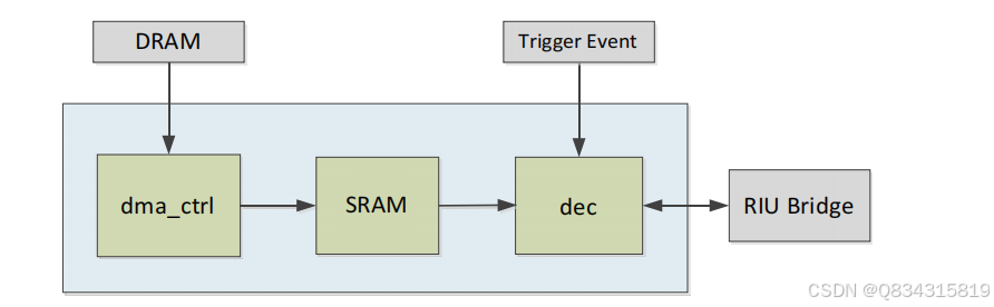
Figure 6-1: Logic Block Diagram of the CMDQ Module
6.3.
Function Description
6.3.1 Dma_ctrl
All commands are stored in memory and three DMA modes are supported for the software to instruct.
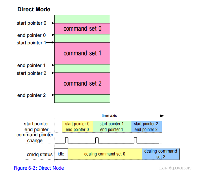
6.3.1.1. Direct
Mode
Direct mode directs the command queue to the absolute DRAM address of start pointer and end pointer. Once
the software has sent a command pointer changed message from RIU to the command queue in this mode, the
command queue will send read requests to DRAM for these data from the start pointer to the end pointer.
Figure 6-2 shows an example of direct mode. When the command queue is at idle state, it receives a command
pointer changed message of command set 0. Then the command queue will set its start and end pointers and
deal with command set 0. While dealing with command set 0, the command queue receives two command
pointer changed messages, command set 1 and command set 2. At this time, only the last one, command set
2, is recorded and executed after finishing command set 0. Therefore, it is best to check the command queue
to see if it is at idle state and then send command pointer changed message when the command queue is idle.
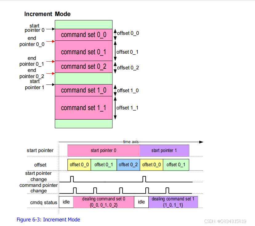
6.3.1.2. Increment
Mode
The second mode is increment mode. This mode uses a start pointer with multiple offsets to let command
queue know how many commands are there. Figure 6-3 shows the increment mode and depicts how to
communicate with the command queue. At first, a start pointer changed message tells the command queue to
change the start pointer. Then, when the command queue receives a command pointer changed message, it
changes the start pointer, start pointer 0, and calculates the end pointer, end pointer 0_0, by adding the offset,
offset 0_0, to the start pointer. By using start pointer and end pointer, the command queue can grab
commands. If a new offset, offset 0_1, comes when the command queue is at idle state, the start pointer will
be replaced by end pointer 0_0 and the new end pointer will be the sum of end pointer 0_0 and offset 0_1.
The increment mode can accept multiple offsets when the command queue is busy. For example, command
pointer changed messages of command sets 0_1 and 0_2 come one by one when the command queue is
dealing with command set 0_0. It will add offset 0_1 and offset 0_2 to a new offset record. When it finishes
command set 0_0, command sets 0_1 and 0_2 will be handled concurrently.
If the start pointer needs to be moved, a start pointer changed message should be sent. Figure 6-3 shows that
a change of start pointer to start pointer 1 is intended, and so the start pointer changed message should be
triggered.
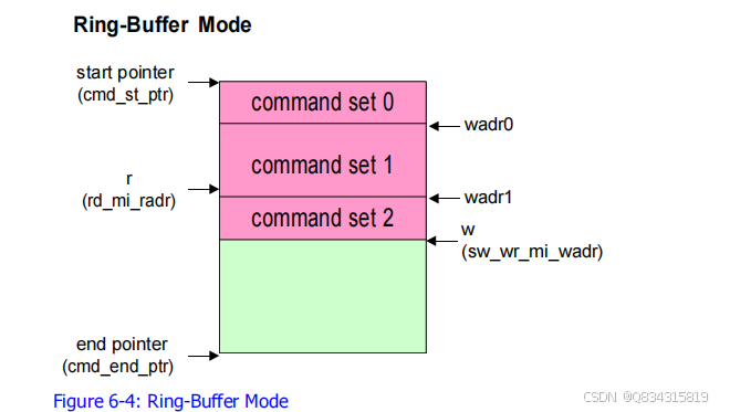
6.3.1.3. Ring-Buffer Mode
The third mode is ring-buffer mode. In Figure 6-4, there are two address pointers, R and W, which move
around a given memory space, limited between start pointer and end pointer. Software tells CMDQ where the
current write pointer (W) is, and the CMDQ will do the command sets that software writes. Once software
finishes storing commands in memory, it needs to write current write address pointer (sw_wr_mi_wadr) and
generate a trigger (mov_cmd_ptr) to inform CMDQ.
If software wants to know where CMDQ is reading, the trigger signal, rd_mi_radr_trig, needs to be sent to
CMDQ to grab current read address pointer (rd_mi_radr).
6.3.2 Dec
Dec module fetches command from SRAM and execute it.
There are five command types, as follows:
Null: do nothing but execute next command.
Write: RIU write command.
Wait: wait for a specified bit of trigger bus and then execute next command.
Polling_eq: read RIU data and check specified bits. If equal, next command will be executed.
Polling_neq: read RIU data and check specified bits. If not equal, next command will be executed.
These five commands have their own format as shown in Figure 6-5 and each occupies 64 bits.