小柴带你学AutoSar系列三、标准和规范篇(4)RTE
目录
1 Introduction
2 RTE Overview
2.1 The RTE in the Context of AUTOSAR
2.2 AUTOSAR Concepts
2.2.1 AUTOSAR Software-components
2.2.2 Basic Software Modules
2.2.3 Communication
2.2.4 Concurrency
2.3 The RTE Generator
2.4 Design Decisions
3 RTE Generation Process
4 RTE Functional Specification
4.1 Architectural concepts
4.2 RTE and Basic Software Scheduler Implementation Aspects
4.2.5 Interrupt decoupling and notifications
4.2.6 Data Consistency
4.3 Communication Paradigms
4.3.1 Sender-Receiver
4.3.2 Client-Server
4.3.3 SWC internal communication
4.3.4 Inter-Partition communication
4.3.5 PortInterface Element Mapping and Data Conversion
4.3.6 Network Representation
4.3.7 Data Conversion
4.3.8 Range Checks during Runtime
4.4 Modes
4.4.1 Mode User
4.4.2 Mode Manager
4.4.3 Refinement of the semantics of ModeDeclarations and Mode
4.4.4 Order of actions taken by the RTE / Basic Software Scheduler upon inter
4.5 External and Internal Trigger
4.6 Initialization and Finalization
4.7 Variant Handling Support
4.7.1 Overview
4.7.2 Choosing a Variant and Binding Variability
4.7.3 Variability affecting the RTE generation
4.7.4 Variability affecting the Basic Software Scheduler generation
4.8 Development error
4.9 Bypass Support
4.9.1 Bypass description
4.9.2 Component wrapper method
4.9.3 Direct buffer access method
4.9.4 Extended buffer access method
4.9.5 Service Based Prototyping
4.10 Data Transformation
5 RTE Reference
5.1 Scope
5.2 API Principles
5.3 RTE Modules
5.4 RTE Data Structures
5.5 API Data Types
5.6 API Reference
5.7 Runnable Entity Reference
5.8 RTE Lifecycle API Reference
5.9 RTE Call-backs Reference
5.10 Expected interfaces
5.11 VFB Tracing Reference
6 Basic Software Scheduler Reference
7 RTE Implementation Plug-Ins Reference
7.1.1 RTE Implementation Plug-Ins in the AUTOSAR Architecture
8 RTE ECU Configuration
2 Functional Overview
4 Requirements on RTE
4.1 Functional Requirements
4.1.1 Interaction with AUTOSAR OS
4.1.2 Interaction with AUTOSAR COM
4.1.3 Interaction with Application Software Component
4.1.4 Interaction with Basic Software Components
4.1.5 Generation of the BSW Scheduler
4.1.6 Support for Measurement and Calibration
4.1.7 General Requirements
4.1.8 VFB Tracing
4.1.9 Application Software Component Initialization and Finalization
4.1.10 API
4.1.11 C/C++ API
4.1.12 Initialization and Finalization Operation
4.1.13 Partition Restarting and Termination
4.1.14 Fault Operation
4.1.15 RTE Implementation Plug-Ins
flechazo![]() https://www.zhihu.com/people/jiu_sheng
https://www.zhihu.com/people/jiu_sheng
小柴带你学AutoSar总目录![]() https://zhuanlan.zhihu.com/p/694169456
https://zhuanlan.zhihu.com/p/694169456
1 Introduction
添加图片注释,不超过 140 字(可选)
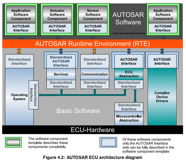
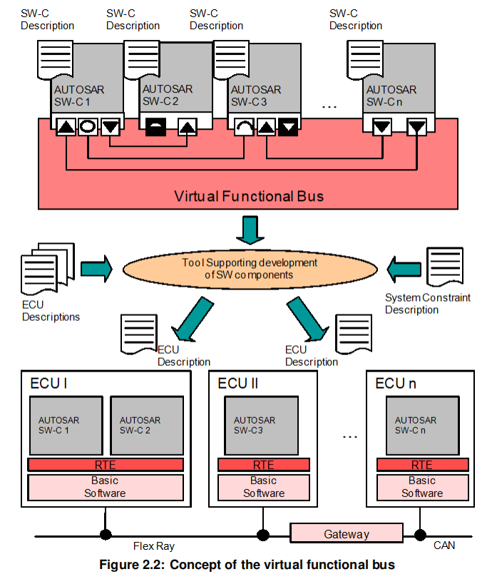
This document contains the software specification of the AUTOSAR Run-Time Environment (RTE) and the Basic Software Scheduler. Basically, the RTE together with the OS, AUTOSAR COM and other Basic Software Modules is the implementation of the Virtual Functional Bus concepts (VFB, [1]). The RTE implements the AUTOSAR Virtual Functional Bus interfaces and thereby realizes the communication between AUTOSAR software-components.
RTE是通信的接口
This document describes how these concepts are realized within the RTE. Further more, the Application Programming Interface (API) of the RTE and the interaction of the RTE with other basic software modules is specified. The Basic Software Scheduler offers concepts and services to integrate Basic Software Modules Hence, the Basic Software Scheduler
-
embed Basic Software Module implementations into the AUTOSAR OS context
-
trigger main processing functions of the Basic Software Modules
-
apply data consistency mechanisms for the Basic Software Modules
-
to communicate modes between Basic Software Modules
在OS中嵌入基础软件
触发主处理函数
数据一致性的机制
基础软件之间的通信模式
flechazowww.zhihu.com/people/jiu_sheng
flechazo:小柴带你学AutoSar总目录6 赞同 · 0 评论文章
2 RTE Overview
2.1 The RTE in the Context of AUTOSAR
In principle the RTE can be logically divided into two sub-parts realizing:
-
the communication between software components
-
the scheduling of the software components
软件组件的通信
软件组件的调度
2.2 AUTOSAR Concepts
2.2.1 AUTOSAR Software-components
In AUTOSAR, “application” software is conceptually located above the AUTOSAR RTE and consists of “AUTOSAR application software-components” that are ECU and location independent and “AUTOSAR sensor-actuator components” that are dependent on ECU hardware and thus not readily relocatable for reasons of performance/efficiency. This means that, subject to constraints imposed by the system designer, an AUTOSAR software-component can be deployed to any available ECU during system configuration. The RTE is then responsible for ensuring that components can communicate and that the system continues to function as expected wherever the components are deployed.
也就是说为了解耦,软件组件可以部署到任意位置,耦合的地方由RTE实现通信/调度。
2.2.2 Basic Software Modules
As well as “AUTOSAR software-components” an AUTOSAR ECU includes basic software modules. Basic software modules can access the ECU abstraction layer as well as other basic software modules directly and are thus neither ECU nor location independent.
BSW可以访问ECU抽象以及其他模块的硬件抽象。
An “AUTOSAR software-component” cannot directly access basic software modules – all communication is via AUTOSAR interfaces and therefore under the control of the RTE. The requirement to not have direct access applies to all Basic Software Modules including the operating system [SRS_Rte_00020] and the communication service.
SWC不可以直接访问BSW,需要通过RTE
2.2.3 Communication
通信是通过port来进行的,具体请看
flechazo:小柴带你学AutoSar系列三、标准和规范篇(1)General4 赞同 · 0 评论文章
The RTE provides different paradigms for the communication between software component instances: sender-receiver (signal passing), client-server (function invocation), mode switch, and NvBlockSwComponentType interaction.
支持的通信方式
-
sender-receiver (signal passing)
-
client-server (function invocation)
-
mode switch
-
NvBlockSwComponentType interaction
Communication Paradigms
Inter-Partition communication occurs between runnable entities in components mapped to different partitions of the same ECU and therefore involve a context switch and crossing a protection boundary (memory protection, timing protection, isolation on a core). Inter-ECU communication occurs between runnable entities in components that have been mapped to different ECUs and so is inherently concurrent and involves potentially unreliable communication.
要作到可靠的通信会涉及几个问题
-
memory protection
-
timing protection
-
isolation on a core
Communication Modes
The RTE supports two modes for sender-receiver communication:
-
Explicit — A component uses explicit RTE API calls to send and receive data elements [SRS_Rte_00098].
-
Implicit — The RTE automatically reads a specified set of data elements before a runnable is invoked and automatically writes (a different) set of data elements after the runnable entity has terminated [SRS_Rte_00128] [SRS_Rte_00129]. The term “implicit” is used here since the runnable does not actively initiate the reception or transmission of data.
分两种一种显式、一种隐式。
显式就是由API主动调用的发送或接收数据
隐式就是类似回调函数这样被自动调用的发送或接收数据

flechazo
1 次咨询
5.0
745 次赞同
去咨询
flechazo:小柴冲刺软考中级嵌入式系统设计师系列总目录1 赞同 · 0 评论文章
Static Communication
预先配置的通信链路
Multiplicity
-
sender-receiver communication
-
支持1:n
-
支持n:1
-
client-server communications
-
仅支持n:1
2.2.4 Concurrency
并发
2.3 The RTE Generator
The RTE generator is one of a set of tools5 that create the realization of the AUTOSAR virtual function bus for an ECU based on information in the ECU Configuration Description. The RTE Generator is responsible for creating the AUTOSAR software component API functions that link AUTOSAR software-components to the OS and manage communication between AUTOSAR software-components and between AUTOSAR software-components and basic software modules.
RTE生成器是创建VFB的工具,负责上下层的交互
2.4 Design Decisions
3 RTE Generation Process
The RTE Generator is used in different roles for the following phases:
-
RTE Contract Phase
-
Basic Software Scheduler Contract Phase
-
PreBuild Data Set Contract Phase
-
Basic Software Scheduler Generation Phase
-
RTE Generation Phase
-
PreBuild Data Set Generation Phase
-
PostBuild Data Set Generation Phase
RTE Generator for Software-Components
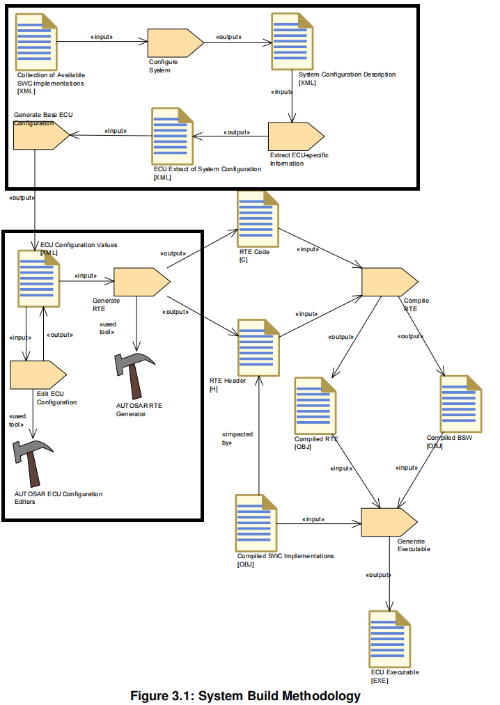
添加图片注释,不超过 140 字(可选)
很显然
-
先描述ECU
-
然后通过配置工具配置,接着生成代码
-
最后编译为可执行文件
下面是一些log信息
The following list is a collection of proposed information items in particular applicable
to log files used for exchanging information about errors.
-
ErrorCode – A symbolic name for the message text
-
StandardErrorCode – The reference to the AUTOSAR error code
-
ConstraintCode – Reference to the semantic constraint mentioned in the AUTOSAR template specification.
-
Signature – Signature of the message for duplicate checks
-
Timestamp – A time stamp for the message
-
ShortName – A unique identification which allows to refer to particular error messages This can also be used to establish references between error messages, e.g. for screening and also to trace back to root cause
-
Desc – The human readable message text
-
Component – Such information item may help the user to locate the problem in the model
-
BaseUrl – An url for a base directory which can be used as basis for file references in a log file. This is typically the root direactory of a project structure.
-
ColumNumber – The column of the error position
-
LineNumber – The line number of the error position
-
LongName – The title of the error message
-
ObjectCategory – The category of for example the involved ApplicationPrimitve DataType (e.g.VALUE)
-
PrimaryErrorReference – Reference to the root cause if applicable
-
ScopeEntryReference – Reference to a scoping message if applicable
-
Object – The shortName based reference to the AUTOSAR element which caused the error
-
ToolName – The name of the tool which reported the error
-
ToolVersion – The version of the tools which reported the error
-
IncidentUrl – The Url which refers to the artifact in which the error occurs
-
Value – The actual found value which caused the problem
RTE Generator for Basic Software Scheduler
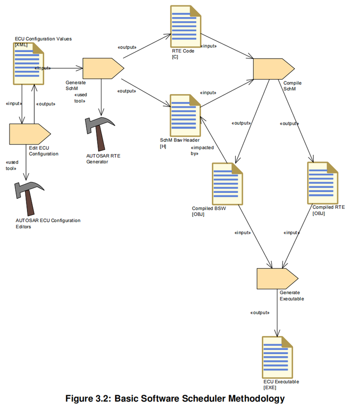
添加图片注释,不超过 140 字(可选)
-
Contract Phase
-
RTE Contract Phase
-
Basic Software Scheduler Contract Phase
-
PreBuild Data Set Contract Phase
-
Edit ECU Configuration of the RTE
-
Generation Phase
-
Basic Software Scheduler Generation Phase
-
RTE Generation Phase
-
Cluster Generation Phase
-
Basic Software Module Description generation
-
Bsw Module Description
-
Bsw Internal Behavior
-
Bsw Implementation
-
Com and LdCom usage
-
Com user generation
-
LdCom user generation
-
PreBuild Data Set Generation Phase
-
PostBuild Data Set Generation Phase
-
RTE Configuration interaction with other BSW Modules
-
The generated RTE interacts heavily with other AUTOSAR Basic Software Modules like Com, LdCom and Os.会和这三个模块有大量的交互
规范这块感觉有点过于细节了
我是没耐心看完哈哈哈
可能只有做RTE生成的工具需要仔细研究
小柴就偷个懒吧
4 RTE Functional Specification
4.1 Architectural concepts
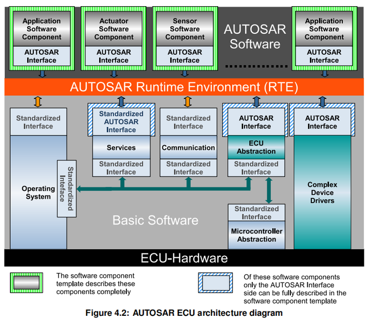
添加图片注释,不超过 140 字(可选)
RTE and Data Types
RTE and AUTOSAR Software-Components
The description of an AUTOSAR software-component is divided into the sections
-
hierarchical structure
-
ports and interfaces
-
internal behavior
-
implementation
AUTOSAR的组件描述分为一下几个
-
层次结构
-
端口和接口
-
内部行为
-
实现
4.2 RTE and Basic Software Scheduler Implementation Aspects
This section describes some specific implementation aspects of an AUTOSAR RTE and the Basic Software Scheduler. It will mainly address
-
the mapping of logical concepts (e.g., Runnable Entities, BSW Schedulable Entities) to technical architectures (namely, the AUTOSAR OS)
-
the decoupling of pending interrupts (in the Basic Software) and the notification of AUTOSAR software components
-
data consistency problems to be solved by the RTE
支持这种链式的task

添加图片注释,不超过 140 字(可选)
RTE事件类型
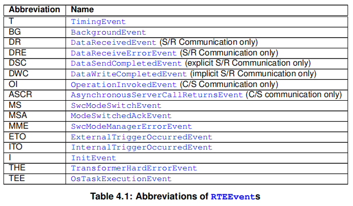
添加图片注释,不超过 140 字(可选)
According to the meta model each kind of RTEEvent can either
ACT activate a RunnableEntity, or
WUP wakeup a RunnableEntity at its WaitPoints

添加图片注释,不超过 140 字(可选)
这里task有几种不同的触发方式
Without OsEvent
void TaskA(void) { RE1(); ActivateTask(TaskB); Schedule(); RE3(); TerminateTask(); } void TaskB(void) { RE2(); TerminateTask(); }
With OsEvent
void TaskA(void) { EventMaskType Event; while(1) { WaitEvent(EvtA | EvtB | EvtC); GetEvent(TaskA, &Event); if (Event & EvtA) { ClearEvent(EvtA); ActivateTask(TaskB); } else if (Event & EvtB) { ClearEvent(EvtB); ActivateTask(TaskC); } else if (Event & EvtC) { ClearEvent(EvtC); ActivateTask(TaskD); } } } void TaskB(void) { RE1(); TerminateTask(); } void TaskC(void) { RE2(); TerminateTask(); } void TaskD(void) { RE3(); TerminateTask(); }
Monitoring of group of runnables
void TaskA(void) { EventMaskType Event; while(1) { WaitEvent(EvtA | EvtB | EvtC); GetEvent(TaskA, &Event); if (Event & EvtA) { ClearEvent(EvtA); RE1(); ActivateTask(TaskB); } else if (Event & EvtB) { ClearEvent(EvtB); RE4(); } else if (Event & EvtC) { ClearEvent(EvtC); RE5(); ActivateTask(TaskC); } } } void TaskB(void) { RE2(); RE3(); TerminateTask(); } void TaskC(void) { RE6(); RE7(): TerminateTask(); }
状态机制
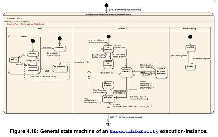
添加图片注释,不超过 140 字(可选)
一个任务的执行周期例子
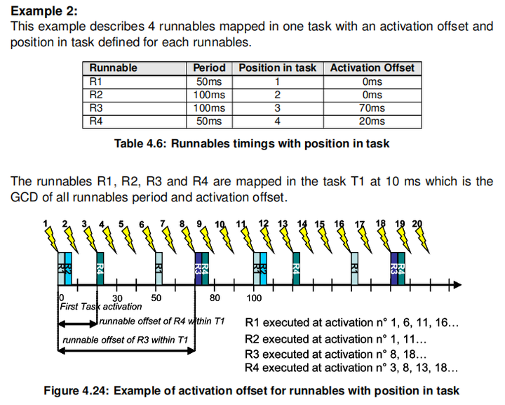
添加图片注释,不超过 140 字(可选)
4.2.5 Interrupt decoupling and notifications
Several of these BSW functionalities create situations, signalled by an interrupt, when AUTOSAR SW-Cs have to be involved. To inform AUTOSAR software components of those situations, runnables in AUTOSAR software components are activated by notifications. So interrupts that occur in the basic software have to be transformed into notifications of the AUTOSAR software components. Such a transformation has to take place at RTE level at the latest! Which interrupt is connected to which notification is decided either during system configuration/generation time or as part of the design of Complex Device Drivers or the Microcontroller Abstraction Layer.
也就是说,中断的向上提醒要在RTE里实现(就是要在RTE里通知SWC哎不对啊,不是说上下啥都要通过RTE吗?那这句是废话了 )
P174页介绍了一堆配置参数
4.2.6 Data Consistency
任务切换会导致数据一致性问题的发生【这块还挺重要的💮】
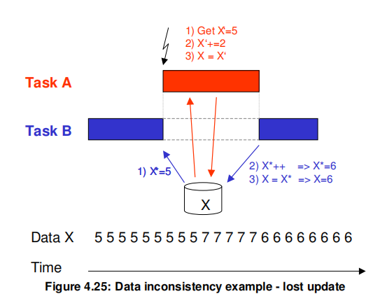
添加图片注释,不超过 140 字(可选)
避免这一问题有一下机制
-
Sequential scheduling strategy
-
顺序调度机制
-
The activation code of Runnables is sequentially placed in one task/ISR2 so that no interference between them is possible because one Runnable is only activated after the termination of the other. Data consistency is guaranteed.
-
Interrupt blocking strategy
-
中断阻塞机制
-
Interrupt blocking can be an appropriate means if collision avoidance is required for a very short amount of time. This might be done by disabling respectively suspending all interrupts, Os interrupts only or - if hardware supports it - only of some interrupt levels. In general this mechanism must be applied with care because it might influence SW in tasks with higher priority too and the timing of the complete system.
-
Usage of OS resources
-
使用OS resources
-
Usage of OS resources. Advantage in comparison to Interrupt blocking strategy is that less SW parts with higher priority are blocked. Disadvantage is that implementation might consume more resources (code, runtime) due to the more sophisticated mechanism. Appropriateness of this mechanism may vary depending on the number of OSs/cores and/or the number of available resources.
-
Task blocking strategy
-
Task阻塞策略
-
Task task preemption is prohibited. This might be reached e.g. by assigning same priorities to affected tasks, by assigning same internal OS resource to affected tasks or by configuring the tasks to be non-preemptive. This mechanismmay be inappropriate in multi-partitioned systems.
-
Copy strategy
-
拷贝策略
-
Idea: The RTE creates copies of data items so that concurrent accesses in different task/ISR2 contexts cannot collide because some of the accesses are redirected to the copies.
-
How it can work:
-
Application for read conflicts:
-
For all readers with lower priority than the writer a read copy is provided.
-
Example:
-
There exist Runnable R1, Runnable R2, data item X and a copy data item X. When Runnable R1 is running in higher priority task context than R2, and R1 is the only one writing X and R2 is reading X it is possible to guarantee data consistency by making a copy of data item X to variable X before activation of R2 and redirecting write access from X to X* or the read access from X to X for R2.
-
Application for write conflicts:
-
If one or more data item receiver with a higher priority than the sender exist, a write copy for the sender is provided.
-
Example:
-
There exist Runnable R1, Runnable R2, data item X and copy data item X.When Runnable R1 (running in lower priority task context than R2) is writing X and R2 is reading X, it is possible to guarantee data consistency by making a copy of data item X to data item X before activation of R1 together with redirecting the write access from X to X* for R1 or the read access from X to X* for R2.
-
Usage of this copy mechanism may make sense if one or more of the following conditions hold:
-
This copy mechanism can handle those cases when only one instance does the data write access.
-
R2 is accessing X several times.
-
More than one Runnable R2 has read (resp. write) access to X.
-
To save runtime is more important than to save code and RAM.
-
Additional RAM requirements to hold the copies is acceptable.
-
Further issues to be taken into account:
-
AUTOSAR SW-Cs provided as source code and AUTOSAR SW-Cs provided as object code may or have to be handled in different ways. The redirecting mechanism for source code could use macros for C and C++ very efficiently whereas object-code AUTOSAR SW-Cs most likely are forced to use references.
Assignment of data consistency mechanisms
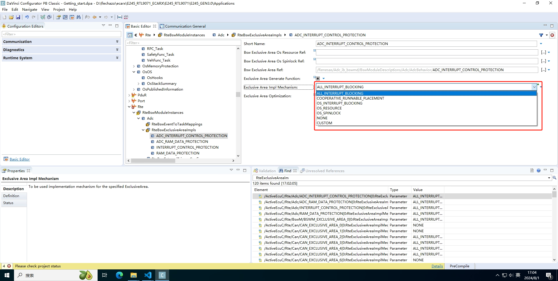
可以在RTE中配置如下几种不同的机制
Actually following values for configuration parameter RteExclusiveAreaImplMechanism must be supported:
-
ALL_INTERRUPT_BLOCKING
This value requests enabling and disabling of all Interrupts and is based on the Interrupt blocking strategy.
-
OS_INTERRUPT_BLOCKING
This value requests enabling and disabling of Os Interrupts and is based on the Interrupt blocking strategy.
-
OS_RESOURCE
This value requests to apply the Usage of OS resources mechanism.
-
OS_SPINLOCK
This value is used to co-ordinate concurrent access by TASKs/ISR2s on different cores to a shared resource.
-
NONE
RTE generator shall not apply any mechanisms for data consistency. Data con sistency will be ensured by methods outside of RTE implementation control.
-
RTE_PLUGIN
This value requests to apply the RTE Implementation Plug-In mechanism.
添加图片注释,不超过 140 字(可选)
4.3 Communication Paradigms
AUTOSAR supports two basic communication paradigms: Client-Server and Sender Receiver. AUTOSAR software-components communicate through well defined ports and the behavior is statically defined by attributes.
AUTOSAR有两种通信模式
-
Client-Server
-
Sender Receiver
The RTE provides the implementation of these communication paradigms. For inter ECU communication the RTE uses the functionalities provided by COM. For inter Partition communication (within the same ECU) the RTE may use functionalities provided by the IOC module. For intra-Partition the RTE provides the functionality on its own.
对于ECU间的通信采用COM模块提供的功能
对应分区间的通信采用IOC模块的功能实现
With Sender-Receiver communication there are two main principles: Data Distribution and Event Distribution.
对于Sender Receiver有两个原则
-
数据分发
-
事件分发
4.3.1 Sender-Receiver
Receive Modes
The RTE supports multiple receive modes for passing data to receivers. The four possible receive modes are:
-
Implicit data read access
-
when the receiver’s runnable executes it shall have access to a “copy” of the data that remains unchanged during the execution of the runnable.
-
当接收器的runnable执行时,它应有权访问在runnable执行期间保持不变的数据的副本
-
Explicit data read access
-
the RTE generator creates a non-blocking API call to enable a receiver to poll (and read) data. This receive mode is an “explicit” mode since an explicit API call is invoked by the receiver.
-
RTE生成器创建非阻塞API调用以使接收器能够poll(和读取)数据。此接收模式为“显示模式,因为接收器调用了显式API调用。
-
wake up of wait point
-
the RTE generator creates a blocking API call that the receiver invokes to read data.
-
RTE生成器创建一个阻塞API调用,接收器调用该API调用来读取数据。
-
activation of runnable entity
-
the receiving runnable entity is invoked automatically by the RTE whenever new data is available. To access the new data, the runnable entity either has to use “implicit data read access” or “explicit data read access”, i.e. invoke an Rte_IRead, Rte_Read, Rte_DRead or Rte_Receive call, depending on the input configuration. This receive mode differs from “implicit data read access” since the receiver is invoked by the RTE in response to a DataReceivedEvent.
-
只要有新数据可用,RTE就会自动调用接收的可运行实体。

添加图片注释,不超过 140 字(可选)
涉及到一些方面
Receive Modes
Multiple Data Elements
Multiple Receivers and Senders
Implicit and Explicit Data Reception and Transmission
Transmission Acknowledgement
Communication Time-out
Data Element Invalidation
Filters
Buffering
Operation
“Never received status” for Data Element
“Update flag” for Data Element
Dynamic data type
Inter-ECU communication through TP
Inter-ECU communication of arrays of bytes
Handling of acknowledgment events
Meta data for application
4.3.2 Client-Server
Multiplicity
Client-server interfaces contain two dimensions of multiplicity; multiple clients invoking a single server and multiple operations within a client-server interface.
客户端-服务器接口包含两个多维度:多个客户端调用单个服务器以及客户端-服务器界面内的多个操作。
Communication Time-out
Port-Defined argument values
Buffering
The buffering mechanisms described here also apply to the serialization of server calls in the Basic Software Scheduler.
这里描述的缓冲机制也适用于基本软件调度程序中的服务器调用的序列化。
也就是对调用的指令进行缓冲,可以同时发送多条指令,服务器这边逐一执行
Inter-ECU and Inter-Partition Response to Request Mapping
Client Identifier
SequenceCounter
Inter-ECU Response Channel Fan-Out
Parameter Serialization
4.3.3 SWC internal communication
Inter Runnable Variables
Sender/Receiver and Client/Server communication through AUTOSAR ports are the model for communication between AUTOSAR SW-Cs.
通过 AUTOSAR端口的发送/接收和客户端/服务器通信是AUTOSAR SW-C之间的通信模型
For communication between Runnables inside of an AUTOSAR SW-C the AUTOSAR SW-C Template [2] establishes a separate mechanism.
对于AUTOSAR SW-C内部的可运行程序之间的通信,AUTOSAR SW-C模板[2]建立一个单独的机制。
But why not use Sender/Receiver communication directly instead? Purpose is data encapsulation / data hiding.
但是为什么不直接使用Sender/Receiver通信呢?目的是数据封装/数据隐藏。
4.3.4 Inter-Partition communication
Partitions are used to decompose an ECU into functional units. Partitions can contain both SW-Cs and BSW modules.
分区用于将ECU分解为功能单元。分区可以包含SW-C模块和BSW模块。
The partitioning is done to protect the software contained in the partitions against each other or to increase the performance by running the partitions on different cores of a multi core controller.
进行分区是为了保护分区中包含的软件相互保护,或者通过在多核控制器的不同核心上运行分区来提高性能。
Inter partition data communication using IOC
The IOC (Inter OS-Application Communication) is a feature of the AUTOSAR OS, which provides a data oriented communication mechanism between partitions.
IOC(Inter OS-Application Communication)是AUTOSAROS的一个特性,它提供了一个面向数据的分区之间的通信机制。
The IOC provides communication buffers, queues, and protected access functions/macros to these buffers that can be used from any pre-configured partitions concurrently.
IOC为这些缓冲区提供通信缓冲区、队列和受保护的访问函数/宏,这些缓冲区内可以同时从任何预先配置的分区使用。
The IOC offers communication of data to another core or between memory protected partitions with guarantee of data consistency.
IOC提供数据到另一个核心或内存保护分区之间的通信,保证数据的一致性。
Inter partition data communication using Basic Software Scheduler
The Basic Software Scheduler provides Sender-Receiver and Client-Server communications mechanisms for communication between Basic Software Modules in different partitions.
基本软件调度器提供发送-接收和客户端-服务器通信机制,用于在不同分区的基本软件模块之间的通信。
Therefore these communication paradigms can be used by Basic Software Modules in a multi core environment.
因此,这些通信范例可以被基本软件模块在多核心环境中使用。
Accessing (Ld)Com and Det in multicore/multipartition configuration
Accessing NvM in multicore/multipartition configurations
Signaling and control flow support for inter partition communication
The OS representation of a partition is an OS Application. This is a (non-exhaustive) summary of OS features that can be used for signaling and control flow across partition boundaries:
这是一个(非详尽的)操作系统功能概述,这些功能可用于跨分区边界的信令和控制流:
-
activation of tasks
-
start and stop of schedule tables
-
event signaling
-
alarms
-
spin locks (for inter core synchronization)
The following are not available for inter core signaling:
-
OS Resource
-
DisableAllInterrupts
For inter core synchronization, spin locks are provided. But, for efficiency reasons they should be used with care.
为了实现核心间同步,提供了自旋锁,但出于效率考虑,应谨慎使用。
Trusted Functions
Memory Protection and Pointer Type Parameters in RTE API
4.3.5 PortInterface Element Mapping and Data Conversion
4.3.6 Network Representation
Network Representation with no data transformation
Network Representation with data transformation
4.3.7 Data Conversion
4.3.8 Range Checks during Runtime
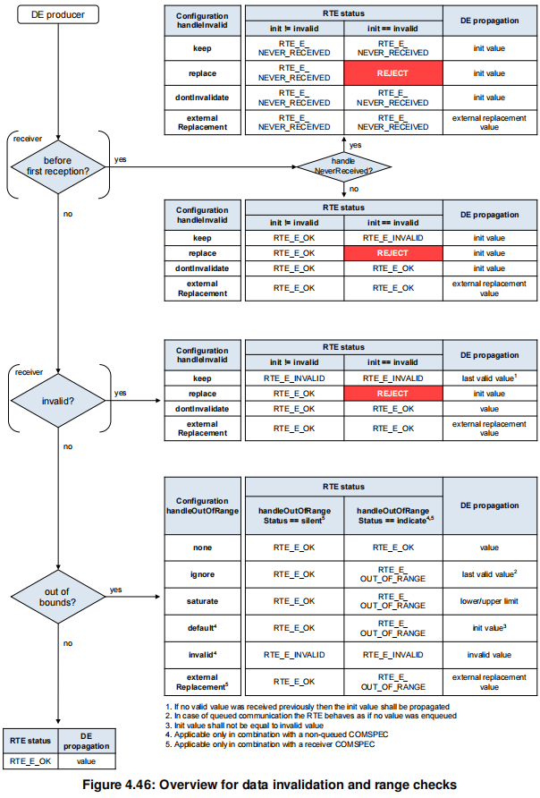
添加图片注释,不超过 140 字(可选)
4.4 Modes
4.4.1 Mode User
The ModeDeclarations can be used in two ways by the mode user
-
Modes can be used to trigger runnables
-
An RTEEvent or BswEvent that starts an ExecutableEntity can contain a mode disabling dependency.
4.4.2 Mode Manager
Entering and leaving modes is initiated by a mode manager.
进入和离开模式由模式管理器启动。
A mode manager might be a basic software module, for example the Basic Software Mode Manager (BswM), the communication manager (ComM), or the ECU state manager (EcuM).
模式管理器可以是基本软件模块,例如基本软件模式管理器(BSWM)、通信管理器(ComM)或ECU状态管理器(EcuM)。
The modemanager may also be an AUTOSAR SW-C. In this case, it is called an application mode manager.
模式管理器也可以是AUTOSAR SW-C。在这种情况下,它被称为应用程序模式管理器。
4.4.3 Refinement of the semantics of ModeDeclarations and Mode
DeclarationGroups
4.4.4 Order of actions taken by the RTE / Basic Software Scheduler upon inter
ception of a mode switch notification
synchronous同步
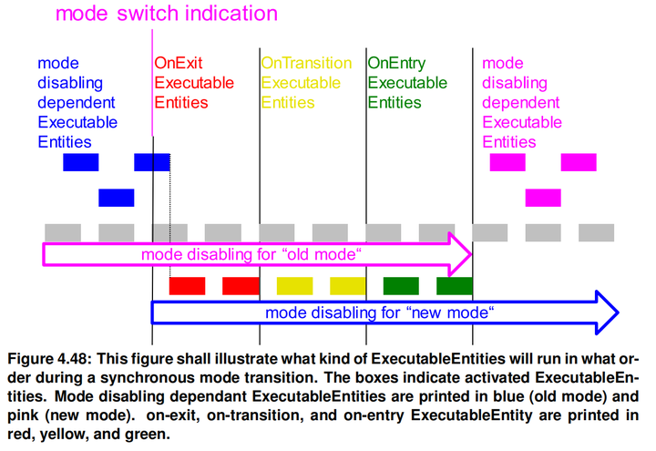
添加图片注释,不超过 140 字(可选)
asynchronous异步
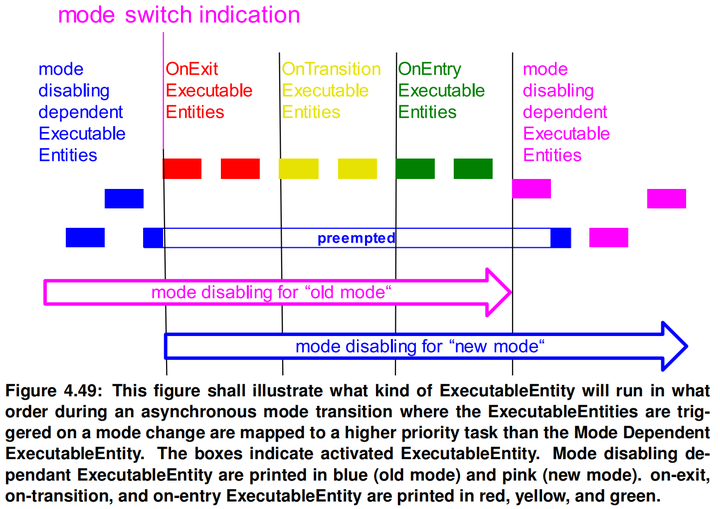
添加图片注释,不超过 140 字(可选)
Assignment of mode machine instances to RTE and Basic Software Scheduler
Initialization of mode machine instances
Notification of mode switches
Mode switch acknowledgment
Mapping of ModeDeclarations
Distributed Shared Mode Queues
4.5 External and Internal Trigger
-
External Trigger Event Communication
-
Trigger Source
-
Multiplicity
-
Multiple Trigger
-
Multiple Trigger Sinks Single Trigger Source
-
Multiple Trigger Sources Single Trigger Sink
-
Synchronized Trigger
Inter Runnable Triggering
-
Multiplicity
Inter Basic Software Module Entity Triggering
Inter ECU Trigger Communication
Queuing of Triggers
Activation of triggered ExecutableEntities
4.6 Initialization and Finalization
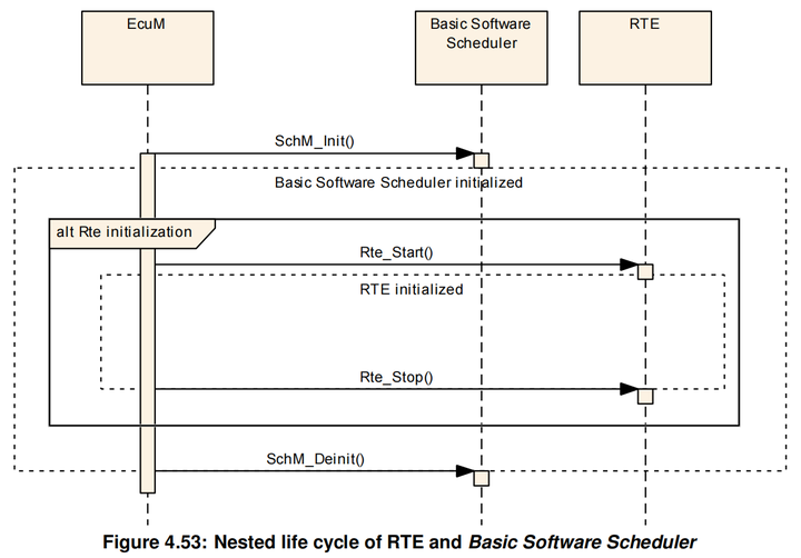
添加图片注释,不超过 140 字(可选)
Initialization of the RTE
Finalization of the RTE
Finalization of the Basic Software Scheduler
Initialization and Finalization of AUTOSAR Software-Components
4.7 Variant Handling Support
4.7.1 Overview
The AUTOSAR Templates support the creation of Variants in a subset of its model elements. The Variant Handling support in the in AUTOSAR Templates is driven by the purpose to describe variability in a AUTOSAR System on several aspects, e.g.
AUTOSAR模板支持在其模型元素子集中创建变体。AUTOSAR模板中的变体处理支持旨在从多个方面描述AUTOSAR系统中的可变性,例如:
-
Virtual Functional Bus
-
Component SwcInternalBehavior and SwcImplementation
-
Deployment of the software components to ECUs
-
Communication Matrix
-
Basic Software Modules
虚拟功能总线 组件外部行为和功能 将软件组件部署到ECU 通信矩阵 基本软件模块
This approach requires that the RTE Generator is able to process the described Variability in input configurations and partially to implement described variability in the generated RTE and Basic Software Scheduler code.
这种方法要求 RTE 生成器能够处理输入配置中描述的变量,并在生成的 RTE 和基本软件调度器代码中部分实现所描述的变量。
4.7.2 Choosing a Variant and Binding Variability
General impact of Binding Times on RTE generation
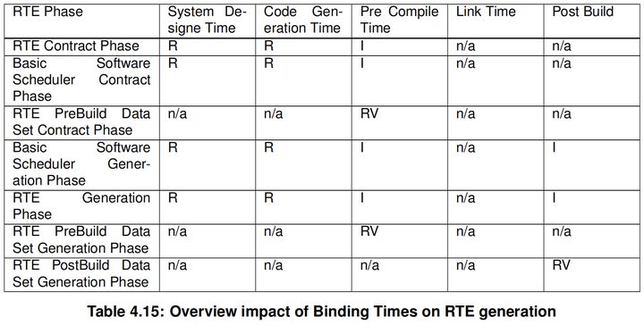
添加图片注释,不超过 140 字(可选)
R resolve variability, a particular variant is the output I implement variability, all possible variants in the output RV provide values to resolve implemented variability PreBuild or PostBuild n/a not applicable
绑定时间对RTE生成的影响
Choosing a particular variant
SystemDesignTime
CodeGenerationTime
PreCompileTime
LinkTime
4.7.3 Variability affecting the RTE generation
Software Composition
Atomic Software Component and its Internal Behavior
-
RTE API which is subject to variability
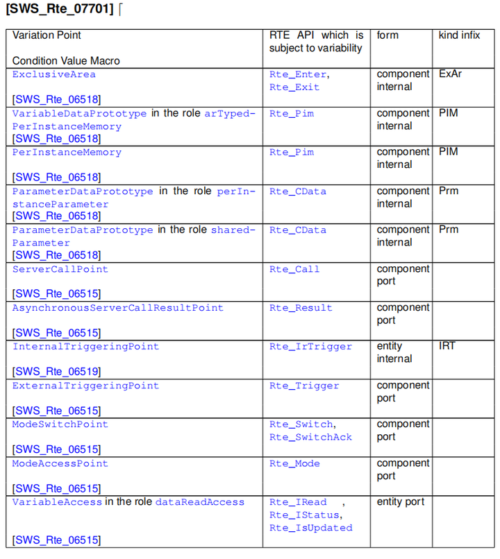
添加图片注释,不超过 140 字(可选)
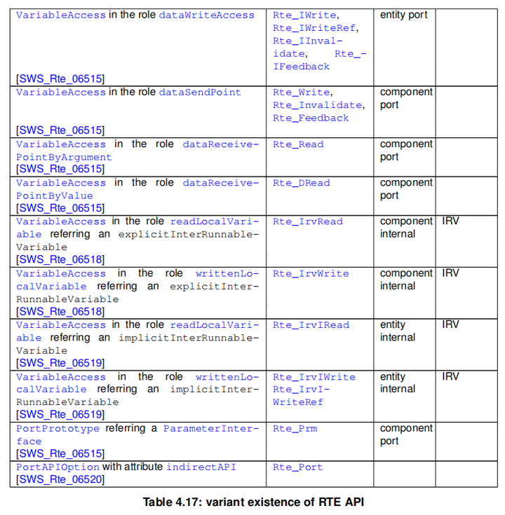
添加图片注释,不超过 140 字(可选)
Conditional API options

添加图片注释,不超过 140 字(可选)
Runnable Entity’s and RTEEvents

添加图片注释,不超过 140 字(可选)
-
Conditional Memory Allocation
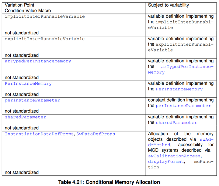
添加图片注释,不超过 140 字(可选)
NvBlockComponent and its Internal Behavior
Parameter Component
Basic Software Modules and its Internal Behavior
Flat Instance descriptor
4.7.4 Variability affecting the Basic Software Scheduler generation
4.8 Development error
4.9 Bypass Support
旁路支持
Rapid prototyping can be used during electronic control unit development to evaluate and test new software control algorithms for various functions.
在电子控制单元开发过程中,可以使用快速原型来评估和测试适用于各种功能的新软件控制算法。
With Fullpass technology the original ECU is totally replaced by a Rapid Prototyping Unit (RPU).
采用 Fullpass 技术,原有的ECU完全被快速原型单元(RPU)所取代。
With Bypass technology the original ECU and software stays in the control loop to supports the majority of the control algorithms and interface with sensors, actuators and communication buses: only the specific control algorithm that shall be prototyped is deported into the RPU (external bypass) or even directly executed in the original ECU (internal bypass).
通过旁路技术,原始ECU和软件留在控制回路中,以支持大多数控制算法并与传感器致动器和通信总线接口:只有应进行原型设计的特定控制算法被发送到RPU(外部旁路)中,甚至直接在原始ECU(内部旁路)中执行。
Bypass mainly consists in replacing at run time inputs and/or outputs of the original software algorithms by value computed by the prototype algorithm under test.
绕过主要包括在运行时用被测试的原型算法计算的值替换原始软件算法的输入和/或输出。
The RTE does not directly implement bypass but the RTE provides supports for the integration of such implementation by CDD and/or integration code.
RTE不直接实现绕过,但RTE支持通过CDD和/或集成代码实现此类实现。
4.9.1 Bypass description
4.9.2 Component wrapper method
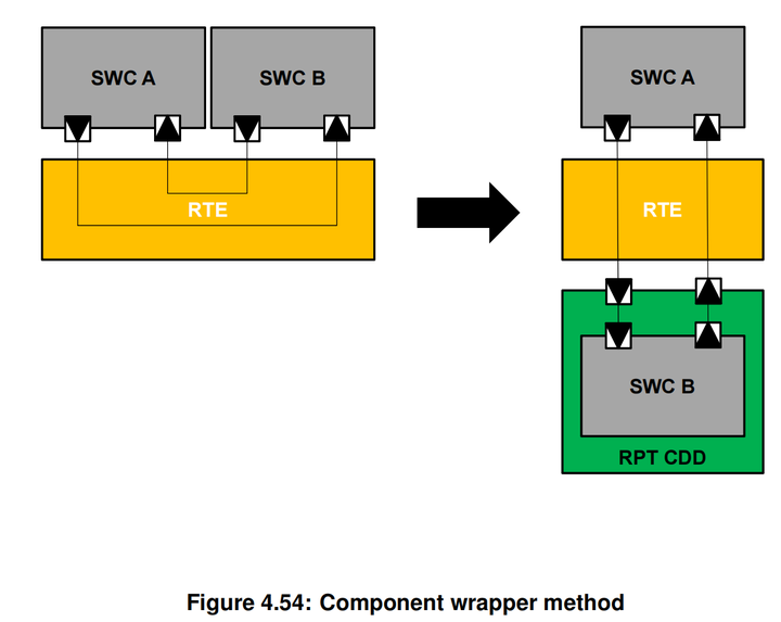
添加图片注释,不超过 140 字(可选)
4.9.3 Direct buffer access method
The direct buffer access method provides runtime direct read and write access to the RTE buffers that implement the ECU communication infrastructure.
直接缓冲区访问方法提供对实现ECU通信基础设施的RTE缓冲区的运行时直接读写访问
4.9.4 Extended buffer access method
The extended buffer access method enhances the support for rapid prototyping (RP) to support the bypass use case where the RTE cannot be regenerated by the bypass user.
扩展缓冲区访问方法增强了对快速原型(RP)的支持,以支持旁路用户无法再生RTE的旁路用例。
The goal is to ensure that all VariableDataPrototypes that are communicated via RTE APIs are written to and read back from a RP global buffer that can be modified by rapid prototyping tools (RPT).
目标是确保所有通过RTE ApI通信的变量数据原型都写入并从RP全局缓冲区读回,该缓冲区可通过快速原型生成工具(RPT)进行修改。
The method applies to all RTE APIs and not just those for implicit access and hence is termed the extended buffer access method.
该方法适用于所有RTE API,而不仅仅是用于隐式访问的API,因此被称为扩展缓冲区访问方法。
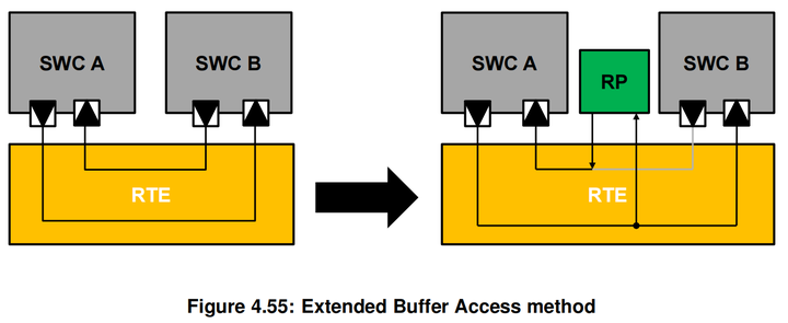
添加图片注释,不超过 140 字(可选)
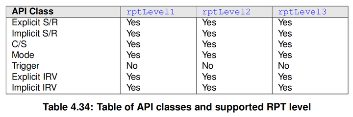
添加图片注释,不超过 140 字(可选)
4.9.5 Service Based Prototyping
Access to the RP global buffers and RP global measurement buffers can be implemented by using a service based ECU interface in which an additional RP service component, such as an “XCP on CAN” or “XCP on Ethernet” service, is added to the ECU application.
可以使用基于服务的ECU接口访问RP全局缓冲区和RP全局测量缓冲区,其中在ECU应用程序中添加了额外的RP服务组件,例如“CAN上的XCP”或“以太网上的XCP”服务
The integration of the service can be performed pre-build by means of source code based integration, for example, by adding an XCP or custom BSW component, or post-build by patching the binary code of an already compiled ECU image.
服务集成可以通过源代码集成(例如,通过添加XCP 或自定义 BSW 组件)进行预构建,也可以通过修补已经编译的 ECU 映像的二进制代码进行后构建。
In a service based scenario data is sampled and/or stimulated at RP service points.
在基于服务的场景中,数据在RP服务点被采样和/或激励。
During either sampling or stimulation the data is read and/or written from the memory associated with the VariableDataPrototype to/from a local buffer during the execution of the RP service point and hence transferred to/from the RP tool.
在采样或刺激期间,在执行 RP 服务点期间,从与VariableDataPrototype 关联的存储器中读取和/或写入本地缓冲区,从而将数据传输到/从 RP 工具。
Within the context of the RTE the data stimulated by the RP service points are the RP global buffers and RP global measurement buffers however any data that is measurable is potentially subject to reading.
在RTE的上下文中,由RP服务点激发的数据是RP全局缓冲区和RP全局测量缓冲区,但是任何可测量数据都可能受到读取。
A RP service point is simply a call of a RP service function that is provided by the RP service component.
RP服务点只是对RP服务组件提供的RP服务函数的调用。
The RP service function is responsible for sampling (reading) and stimulating (writing) the bypass data.
RP服务功能负责对旁路数据进行采样(读取)和激励(写入)。
The action of sampling may then trigger the RP system to perform the bypass (this may involve the communication of the sampled data to an external system for computation) ready for reading when the stimulation occurs.
采样操作可能会触发 RP 系统执行旁路操作(这可能涉及将采样数据传送到外部系统进行计算),以便在刺激发生时进行读取。
4.10 Data Transformation
Transformers enable AUTOSAR systems to use a data transformation mechanism to linearize and transform data.
废话一条
They can be concatenated to transformer chains and are executed by the RTE for inter-ECU communication which is configured to be transformed.
它们可以连接到转换器链,并由用于ECU间通信的RTE执行,ECU间通信被配置为被转换的
The input of the first transformer in the chain gets the data from the RTE.Each following transformer uses the output of the preceding transformer as input.
链中第一个转换器的输入从RTE获得数据,随后的每个转换器使用前一个转换器的输出作为输入
All transformers following the first one then have a generic signature with just a byte array as IN and OUT parameter. Such an architecture could be used to design systems, where you can flexibly add functionality like safety or security protection to a serialized stream.
第一个转换器之后的所有转换器都有一个通用的签名,只有字节数组作为IN和 OUT参数。这样的架构可以用来设计系统,您可以在串行流中灵活地添加安全或安全保护等功能。
The transformers for inter-ECU communication are configured in the System Description.
用于ECU间通信的转换器在系统说明中配置。
Furthermore the RTE can execute transformers for intra-ECU communication to transform different representations of data structures between software components or basic software modules within one ECU.
此外,RTE可以执行用于ECU内部通信的转换器,以转换一个ECU内软件组件或基本软件模块之间的不同数据结构表示。
Transformers for intra-ECU communication are restricted to unqueued S/R communication. In addition no transformer chains are applicable.
用于ECU内部通信的转换器仅限于非排队的S/R通信。此外,不适用转换器链。
Those limitations are formulated since for the currently known use-cases there is no need for introducing this functionality.
之所以制定这些限制,是因为对于目前已知的用例,没有必要引入此功能。
The execution of the transformers and the necessary buffer handling is coordinated by the RTE.
转换器的运行和必要的缓冲处理由RTE进行协调。
Execution of Transformer
Transformer for inter-ECU communication
Transformer for intra-ECU communication
Transformer Chains
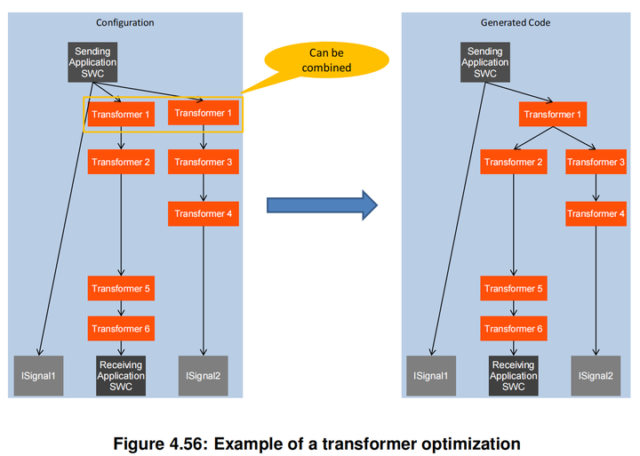
添加图片注释,不超过 140 字(可选)
Buffer Handling
Interfaces to Transformer
Error Handling
Transformer Code Forwarding
There exist use-cases where the application software needs to influence the behavior of the sending transformer chain.
存在应用软件需要影响发送转换器链的行为的用例。
One prominent example is a signal to service translation application where the forwarding of E2E status information into the E2E Transformer on the sending side is required.
一个突出的例子是信号到服务转换应用程序,其中需要将E2E状态信息转发到发送端的E2E转换器。
In case E2E protection is to be applied for a communication path with signal to service translation on the way, then the E2E status assessed for the received data needs to be forwarded to the E2E information generated for the sending side.
如果E2E保护应用于具有信号到服务转换的通信路径,则需要对接收到的数据进行评估的E2E状态需要转发到为发送方生成的E2E信息。
Thus the application which is going to use the data can identify data exchange faults by using the standard E2E check function.
因此,将要使用数据的应用程序可以使用标准的E2E检查功能来识别数据交换故障。
Transformer Transaction Handling
Transformer Protocol Header Peeking
COM Based Transformer
The COM Based Transformer approach is an alternative transformation handling whic has several aspects:
基于COM的转换器方法是一种可选的转换处理方法,它有以下几个方面
-
the first transformer is the ’COM Based Transformer’ [24] for the ’serialization’ of data,
-
the further transformers are invoked normally and enhance the array representation of the data element,
-
the handling of the transformed data towards the COM Module [3] is done via a specific array based signal group API.
第一个转换器是“基于COM的Transformer”[24]对于数据的“序列化“
进一步变换器被正常调用并增强数据元素的阵列表示,
向COM模块转换数据的处理[3]是通过特定的基于阵列的信号组API来完成的。
The ’COM Based Transformer’ [24] serializes the data elements into the array representation exactly as the COM module would have done it.
基于COM的转换器[24]正如COM模块所做的那样,将数据元素序列化为数组表示形式。
The System Template [8] provides means to define which data elements shall be handled by the ’COM Based Transformer’ and - via the communication matrix section - also how the data shall be serialized.
系统模板[8]提供了定义哪些数据元素应该由“基于COM的Transformer”处理的方法,以及--通过通信矩阵部分--数据应该如何序列化。
This is the basis for the COM module’s configuration and ’COM Based Transformer’ behavior. The RTE interacts with the COM module via dedicated array based signal group APIs for sending and receiving the transformed data.
这是COM模块配置和“基于COM的Transformer”行为的基础。 RTE通过专用的基于阵列的信号组API与COM模块交互,用于发送和接收转换数据。
5 RTE Reference
“Everything should be as simple as possible, but no simpler.” – Albert Einstein
5.1 Scope
-
5.1.1 Programming Languages
-
5.1.2 Generator Principles
-
Operating Modes
-
Compatibility Mode
-
Vendor Mode
-
Optimization Modes
-
Build support
-
Software Component Namespace
-
5.1.3 Generator external configuration switches
-
Unconnected R-Port check
-
Missing input configuration check
-
Missing initialization values
5.2 API Principles
The design of the RTE API has been guided by the following core principles:
-
The API should be orthogonal – there should be only one way of performing a task.
-
[SWS_Rte_01314] The API shall be compiler independent. (SRS_Rte_00100)
-
[SWS_Rte_01315] The API shall support components where the source code is available [SRS_Rte_00024] and where only object-code is available [SRS_Rte_00140].(SRS_Rte_00024, SRS_Rte_00140**)
-
The API shall support the multiple instantiation of AUTOSAR software components [SRS_Rte_00011] that share code [SRS_Rte_00012].
RTE API的设计遵循以下核心原则:
-
API应该是正交的--执行任务应该只有一种方法
-
[SWS_Rte_01314] API应与编译器无关。(SRS_Rte_00100)
-
[SWS_Rte_01315] API应支持源代码可用的组件[SRS_Rte_00024]和只有对象代码可用的组件[SRS Rte_00140].c(SRS Rte_00024,SRS_Rte_00140**)
-
API应支持共享代码「SRS Rte 00012]的 AUTOSAR软件组件[SRS Rte00011]的多个实例化。
Two forms of the RTE API are available to software-components; direct and indirect.
软件组件可以使用两种形式的RTE API:直接和间接。
The direct API has been designed with regard to efficient invocation and includes an API mapping that can be used by an RTE generator to optimize a component’s API, for example, to permit the direct invocation of the generated API functions or even eliding the generated RTE completely.
直接API的设计考虑了高效的调用,并包括一个API映射,RTE生成器可以使用它来优化组件的API,例如,允许直接调用生成的API函数,甚至完全省略生成的RTE。
The indirect API cannot be optimized using the API mapping but has the advantage that the handle used to access the API can be stored in memory and accessed, via an iterator, to apply the same API to multiple ports.
间接 API不能使用 API映射进行优化,但它具有优势,即用于访问 API的句柄可以存储在内存中,并通过迭代器进行访问,以将相同的 API应用于多个端口。
嗯这个真的是很常用,会将整个代码的逻辑梳理的很清晰
给个例子吧
void (*fuck[10])(int) = { PipeLine_CheckPointer, PipeLine_CheckStatus, PipeLine_EnterProtectionArae }; int main(){ }
就这样吧
5.2.1 RTE Namespace
5.2.2 Direct AP
5.2.3 Indirect API
5.2.4 VariableAccess in the dataReadAccess and dataWriteAccess roles
5.2.5 Per Instance Memory
5.2.6 API Mapping
5.2.7 Unconnected Ports
5.2.8 Non-identical port interfaces
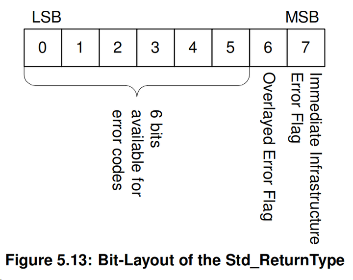
5.2.9 Return type Std_ReturnType
5.3 RTE Modules
5.4 RTE Data Structures
5.5 API Data Types
5.5.1 Std_ReturnType
添加图片注释,不超过 140 字(可选)
5.6 API Reference
5.7 Runnable Entity Reference
5.8 RTE Lifecycle API Reference
5.9 RTE Call-backs Reference
5.10 Expected interfaces
5.11 VFB Tracing Reference
6 Basic Software Scheduler Reference
7 RTE Implementation Plug-Ins Reference
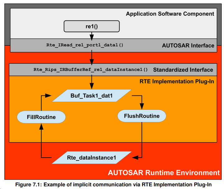
7.1.1 RTE Implementation Plug-Ins in the AUTOSAR Architecture
添加图片注释,不超过 140 字(可选)
8 RTE ECU Configuration
2 Functional Overview
The Run-Time Environment (RTE) is at the heart of the AUTOSAR ECU architecture. The RTE is the realization (for a particular ECU) of the interfaces of the AUTOSAR Virtual Function Bus (VFB) and thus provides the infrastructure services for communication between Application Software Components as well as facilitating access to basic software components including the OS.
RTE是VFB的实现,为应用软件组件之间提供通信,SWC与BSW之间的交互
4 Requirements on RTE
4.1 Functional Requirements
4.1.1 Interaction with AUTOSAR OS
[SRS_Rte_00020] Access to OS
[SRS_Rte_00099] Decoupling of interrupts
[SRS_Rte_00036] Assignment to OS Applications
[SRS_Rte_00049] Construction of task bodies
[SRS_Rte_00193] Support for Runnable Entity execution chaining
[SRS_Rte_00210] Support for inter OS application communication
4.1.2 Interaction with AUTOSAR COM
[SRS_Rte_00068] Signal initial values
[SRS_Rte_00069] Communication timeouts
[SRS_Rte_00073] Atomic transport of Data Elements
[SRS_Rte_00082] Standardized communication protocol
[SRS_Rte_00091] Inter-ECU Marshalling
[SRS_Rte_00181] Conversion between internal and network data types
[SRS_Rte_00246] Support of Efficient COM for large data
[SRS_Rte_00251] Array based signal group handling with Com
[SRS_Rte_00322] Support of Metadata
4.1.3 Interaction with Application Software Components
[SRS_Rte_00011] Support for multiple Application Software Component instances.
[SRS_Rte_00012] Multiple instantiated AUTOSAR software components delivered as binary code shall share code
[SRS_Rte_00013] Per-instance memory
[SRS_Rte_00077] Instantiation of per-instance memory
[SRS_Rte_00017] Rejection of inconsistent component implementations
[SRS_Rte_00134] Runnable Entity categories supported by the RTE
[SRS_Rte_00072] Activation of Runnable Entities
RTE要根据事件触发任务
[SRS_Rte_00160] Debounced start of Runnable Entities
消抖,短时间内只触发一次
[SRS_Rte_00161] Activation offset of Runnable Entities
[SRS_Rte_00031] Multiple Runnable Entities
[SRS_Rte_00032] Data consistency mechanisms
数据一致性的机制
[SRS_Rte_00046] Support for "Executable Entity runs inside" Exclusive Areas
[SRS_Rte_00142] Support for InterRunnableVariables
[SRS_Rte_00033] Serialized execution of Server Runnable Entities
RTE支持运行实体的序列化执行
[SRS_Rte_00133] Concurrent invocation of Runnable Entities
可并发
[SRS_Rte_00143] Mode Switches
[SRS_Rte_00176] Sharing of NVRAM data
[SRS_Rte_00180] DataSemantics range check during runtime
支持一些数据的检查
[SRS_Rte_00182] Self Scaling Signals at Port Interfaces
[SRS_Rte_00236] Support for ModeInterfaceMapping
[SRS_Rte_00237] Time recurrent activation of Runnable Entities
可定时循环激活运行实体
4.1.4 Interaction with Basic Software Components
[SRS_Rte_00152] Support for port-defined argument values
[SRS_Rte_00022] Interaction with call-backs
[SRS_Rte_00062] Local access to basic software components
支持本地通过BSW,也可以远程通过其他ECU的BSW
[SRS_Rte_00169] Map code and memory allocated by the RTE to memory sections
[SRS_Rte_00170] Provide used memory sections description
[SRS_Rte_00177] Support of NvBlockComponentType
[SRS_Rte_00228] Fan-out NvBlock callback function
[SRS_Rte_00233] Generation of the Basic Software Module Description
[SRS_Rte_00241] Support for Local or Remote Handling of BSW Service Calls on Partitioned Systems
For systems where the BSW modules can be executed in multiple partitions, the RTE generator shall redirect the BSW service call from a SWC either to the local or to a remote partition based on the partition mapping(s) assigned to the BSW Module.
[SRS_Rte_00245] Support of Writing Strategies for NV data
4.1.5 Generation of the BSW Scheduler
[SRS_Rte_00211] Cyclic time based scheduling of BSW Schedulable Entities
[SRS_Rte_00212] Activation Offset of BSW Schedulable Entities
[SRS_Rte_00213] Mode Switches for BSW Modules
[SRS_Rte_00214] Common Mode handling for Basic SW and Application SW
[SRS_Rte_00215] API for Mode switch notification to the SchM
[SRS_Rte_00216] Triggering of BSW Schedulable Entities by occurrence of External Trigger
支持外部的触发源
[SRS_Rte_00230] Triggering of BSW Schedulable Entities by occurrence of Internal Trigger
[SRS_Rte_00217] Synchronized activation of Runnable Entities and BSW Schedulable Entities
[SRS_Rte_00218] API for Triggering BSW modules by Triggered Events
[SRS_Rte_00219] Support for interlaced execution sequences of Runnable Entities and BSW Schedulable Entities
[SRS_Rte_00220] ECU life cycle dependent scheduling
[SRS_Rte_00221] Support for "BSW integration" builds
[SRS_Rte_00222] Support shared exclusive areas in BSW Service Modules and the corresponding Service Component
[SRS_Rte_00229] Support for Variant Handling of BSW Modules
[SRS_Rte_00243] Support for inter-partition communication of BSW modules
4.1.6 Support for Measurement and Calibration
[SRS_Rte_00153] Support for Measurement
[SRS_Rte_00154] Support for Calibration
[SRS_Rte_00156] Support for different calibration data emulation methods
The RTE generator shall support these data emulation methods for calibration purposes: directAccess Calibration data is stored in ROM and accessed directly. This method can be used with appropriate calibration hardware. Single pointered method Calibration data accesses are done via one indirection over a pointer table in RAM Double pointered method Calibration data accesses are done via a base pointer in RAM and over a pointer table in ROM/FLASH InitRAM parameter method RTE accesses calibration parameters located in RAM directly (without any indirection) and copies the values from ROM/FLASH during startup Methods 2-4 need SW support from RTE.
要支持数据校准
[SRS_Rte_00157] Support for calibration parameters in NVRAM
[SRS_Rte_00158] Support separation of calibration parameters
[SRS_Rte_00159] Sharing of calibration parameters
[SRS_Rte_00189] A2L Generation Support
4.1.7 General Requirements
[SRS_Rte_00021] Per-ECU RTE customization
The RTE shall be customizable (generated and/or configured) for each ECU. The RTE generator should avoid, where possible, the use of generic functions and should, instead, favor functions that are configured/generated to specifically implement the required communication patterns.
RTE应该客制化,配置化,尽量避免使用通用的API
[SRS_Rte_00065] Deterministic generation
[SRS_Rte_00028] "1:n" Sender-receiver communication
[SRS_Rte_00131] "n:1" Sender-receiver communication
[SRS_Rte_00029] "n:1" Client-server communication
The RTE shall support multiple-client-single-server ("n:1") client-server (function invocation) communication. Individual clients are independent - there is no coordination of requests between clients. Single-client-multiple-server ("1:n") communication is not required. Such communication raises issues about buffering and selection of results that are application dependent and therefore not considered to be the domain of the RTE.
不需要单客户端多服务端
[SRS_Rte_00079] Single asynchronous client-server interaction
一次只支持单个的异步交互
[SRS_Rte_00080] Multiple requests of servers
支持多个客户端对服务端的并发请求,服务端进行请求队列排队
[SRS_Rte_00162] "1:n" External Trigger communication
[SRS_Rte_00163] Support for InterRunnableTriggering
[SRS_Rte_00235] Support queued triggers
[SRS_Rte_00025] Static communication
The RTE shall support only those communication connections known when the RTE is generated - the source(s) and destination(s) of all communication shall be known statically
也就是说,服务器端的接口都是定义好的,都是静态的。只有订阅者是动态的。
[SRS_Rte_00144] RTE shall support the notification of mode switches via AUTOSAR interfaces
定义好接口机制,在模式切换时做好trace函数接口
[SRS_Rte_00018] Rejection of invalid configurations
[SRS_Rte_00055] RTE use of global namespace
All symbols use the prefix "RTE".
[SRS_Rte_00164] Ensure a unique naming of generated types visible in the global namespace
[SRS_Rte_00165] Suppress identical "C" type re-definitions
[SRS_Rte_00166] Use the AUTOSAR Standard Types in the global namespace if the AUTOSAR data type is mapped to an AUTOSAR Standard Type
[SRS_Rte_00167] Encapsulate a Software Component local name space
[SRS_Rte_00252] Encapsulate a BSW Module local name space
[SRS_Rte_00126] C language support
[SRS_Rte_00138] C++ language support
[SRS_Rte_00051] RTE API mapping
[SRS_Rte_00048] RTE Generator input
[SRS_Rte_00023] RTE Overheads
[SRS_Rte_00024] Source-code AUTOSAR software components
[SRS_Rte_00140] Binary-code AUTOSAR software components
[SRS_Rte_00083] Optimization for source-code components
[SRS_Rte_00027] VFB to RTE mapping shall be semantic preserving
[SRS_Rte_00190] Support for variable-length Data Types
[SRS_Rte_00234] Support for Record Type sub-setting
4 wheel speed signals and the movement direction signal are provided in one record. If a receiver is only interested in the movement direction information all of the other information from this record does not have to be considered at this specific receiver.
[SRS_Rte_00098] Explicit Sending
[SRS_Rte_00129] Implicit Sending
[SRS_Rte_00128] Implicit Reception
[SRS_Rte_00141] Explicit Reception
[SRS_Rte_00092] Implementation of VFB model "waitpoints"
支持等待点,事件触发后继续执行
[SRS_Rte_00145] Compatibility mode
[SRS_Rte_00146] Vendor mode
有一个供应商的操作模式
[SRS_Rte_00148] Support "Specification of Memory Mapping"
[SRS_Rte_00150] Support "Specification of Platform Types"
[SRS_Rte_00151] Support RTE relevant requirements of the "General Requirements on Basic Software Modules"
[SRS_Rte_00171] Support for fixed and constant data
[SRS_Rte_00178] Data consistency of NvBlockComponentType
[SRS_Rte_00179] Support of Update Flag for Data Reception
有个标志位来标识是否有数据更新
[SRS_Rte_00184] RTE Status "Never Received"
[SRS_Rte_00191] Support for Variant Handling
[SRS_Rte_00201] Contract Phase with Variant Handling support
[SRS_Rte_00202] Support for array size variants
[SRS_Rte_00204] Support the selection / de-selection of SWC prototypes
[SRS_Rte_00206] Support the selection of a signal provider
[SRS_Rte_00207] Support N to M communication patterns while unresolved variations are affecting these communications
[SRS_Rte_00231] Support native interface between Rte and Com for Strings and uint8 arrays
[SRS_Rte_00232] Synchronization of runnable entities
[SRS_Rte_00238] Allow enabling of RTE-Feature to get the activating Event of Executable Entity
[SRS_Rte_00244] Support for bypass
[SRS_Rte_00254] Selectable RP Preparation
[SRS_Rte_00255] RP Memory Interface
[SRS_Rte_00256] Conditional Bypass
[SRS_Rte_00257] RunnableEntity Bypass
[SRS_Rte_00258] RTE Generated Service Points
[SRS_Rte_00259] Manually Inserted Service Points
[SRS_Rte_00260] RP Interface Documentation
[SRS_Rte_00247] The Rte shall execute transformer chains for SWC communication
[SRS_Rte_00248] The Rte shall provide the buffer for the data transformation
[SRS_Rte_00249] The Rte shall provide transformation errors to the SWCs
[SRS_Rte_00253] The RTE shall execute data transformation for SWC/BSW communication within one ECU
[SRS_Rte_00250] The Rte shall provide size indications of variable size arrays to SWCs
对可变大小的数组要指示出长度信息
[SRS_Rte_00261] The RTE shall support optional struct members.
4.1.8 VFB Tracing
[SRS_Rte_00005] The RTE generator shall support "trace" builds
支持trace,这里会有很多接口来追踪代码
[SRS_Rte_00045] Standardized VFB tracing interface
[SRS_Rte_00008] VFB tracing configuration
[SRS_Rte_00192] Support multiple trace clients
[SRS_Rte_00003] Tracing of sender-receiver communication
[SRS_Rte_00004] Tracing of client-server communication
4.1.9 Application Software Component Initialization and Finalization
[SRS_Rte_00052] Initialization and finalization of components
[SRS_Rte_00070] Invocation order of Runnable Entities
[SRS_Rte_00239] Support rule-based initialization of composite DataPrototypes and compound primitive DataPrototypes
[SRS_Rte_00240] Support of init runnables for initialization purposes
4.1.10 API
[SRS_Rte_00100] Compiler independent API
[SRS_Rte_00168] Typing of RTE API.
[SRS_Rte_00059] RTE API shall pass "in" primitive data types by value
[SRS_Rte_00060] RTE API shall pass "in" composite data types by reference
Pass by reference is efficient for large data types.
[SRS_Rte_00061] "in/out" and "out" parameters
The RTE API shall pass ‘in/out’ and "out" formal parameters by reference.
[SRS_Rte_00115] API for data consistency mechanism
[SRS_Rte_00075] API for accessing per-instance memory
[SRS_Rte_00107] Support for INFORMATION_TYPE attribute
[SRS_Rte_00108] Support for INIT_VALUE attribute
[SRS_Rte_00109] Support for RECEIVE_MODE attribute
[SRS_Rte_00110] Support for BUFFERING attribute
[SRS_Rte_00111] Support for CLIENT_MODE attribute
[SRS_Rte_00121] Support for FILTER attribute
[SRS_Rte_00147] Support for communication infrastructure time-out notification
[SRS_Rte_00078] Support for Data Element Invalidation
[SRS_Rte_00122] Support for Transmission Acknowledgement
[SRS_Rte_00094] Communication and Resource Errors
[SRS_Rte_00084] Support infrastructural errors
[SRS_Rte_00123] The RTE shall forward application level errors from server to client
[SRS_Rte_00124] API for application level errors during Client Server communication
[SRS_Rte_00089] Independent access to interface elements
[SRS_Rte_00137] API for mismatched ports
[SRS_Rte_00139] Support for unconnected ports
[SRS_Rte_00200] Support of unconnected R-Ports
[SRS_Rte_00155] API to access calibration parameters
[SRS_Rte_00183] RTE Read API returning the dataElement value
[SRS_Rte_00185] RTE API with Rte_IFeedback
[SRS_Rte_00203] API to read system constant
[SRS_Rte_00242] Support for Cross-Core Exclusive Areas
4.1.11 C/C++ API
[SRS_Rte_00087] Software Module Header File generation
4.1.12 Initialization and Finalization Operation
[SRS_Rte_00116] RTE Initialization and finalization
4.1.13 Partition Restarting and Termination
[SRS_Rte_00196] Inter-partition communication consistency
4.1.14 Fault Operation
4.1.15 RTE Implementation Plug-Ins
[SRS_Rte_00318] Modular Runtime Environment
[SRS_Rte_00300] RTE Implementation Plug-Ins for explicit communication
The RTE shall support to implement for explicit communication following subfunctionality • getting a semaphore • releasing a semaphore • implementation of the semaphore • accessing the global copy of the data • invocation of transformers • APIs to enable the communication across different ASIL levels • APIs to enable the communication between Software Clusters via RTE Implementation Plug-Ins outside the RTE Generator. This includes port based communication as well as Inter Runnable Variables.
[SRS_Rte_00301] RTE Implementation Plug-Ins for implicit communication
[SRS_Rte_00320] RTE Implementation Plug-Ins for implicit communication II
[SRS_Rte_00302] RTE Implementation Plug-Ins for exclusive areas
[SRS_Rte_00303] RTE Implementation Plug-Ins for global copy instantiation
[SRS_Rte_00304] Multiple RTE Plug-Ins
[SRS_Rte_00305] Graduated validation strategy
[SRS_Rte_00306] Standardized interfaces for RTE Implementation Plug-Ins
[SRS_Rte_00307] RTE Implementation Plug-Ins for cross core communication
[SRS_Rte_00309] RTE Implementation Plug-Ins for cross safety partition communication
[SRS_Rte_00310] Shared mode queue
[SRS_Rte_00311] Core synchronous transitions for mode switches
[SRS_Rte_00312] RTE Implementation Plug-Ins for transformers in client server communication
[SRS_Rte_00317] RTE Implementation Plug-Ins for transformers in trigger communication
[SRS_Rte_00319] RTE Implementation Plug-Ins for parameter communication
[SRS_Rte_00313] Description of RTE Implementation Plug-in properties
[SRS_Rte_00314] Avoid nesting of critical sections
[SRS_Rte_00315] Protection of mode machine instance access
[SRS_Rte_00321] RTE Implementation Plug-Ins for mode communication
[SRS_Rte_00316] RTE Implementation Plug-Ins for compatibility mode
