HCIP VRRP MSTP 交换综合实验
1.拓扑图

2.实验要求
1.内网IP地址使用172.16.0.0/16分配
2.sw1和sw2之间互为备份
3.VRRP/STP/VLAN/Eth-trunk均使用
4.所以PC均通过DHCP获取IP地址
5.ISP只能配置地址
6.所以电脑可以正常访问Isp路由器环回
3.实验需求大纲
1.首先需要划分网段以及分配IP地址
2.使用vrrp和mstp互为备份
3.需要使用动态路由或者静态路由以及nat
4.对isp做环回和配IP地址
4.具体步骤
1.sw3---将各个接口对vlan2 3 进行划分以及通过
vlan batch 2 to 3
[sw3-GigabitEthernet0/0/1]dispaly this
interface GigabitEthernet0/0/1
port hybrid pvid vlan 2
port hybrid untagged vlan 2
[sw3-GigabitEthernet0/0/2]dispaly this
interface GigabitEthernet0/0/2
port hybrid pvid vlan 3
port hybrid untagged vlan 3
[sw3-GigabitEthernet0/0/3]dis this
interface GigabitEthernet0/0/3
port link-type trunk
port trunk allow-pass vlan 2 to 3
[sw3-GigabitEthernet0/0/4]dis this
interface GigabitEthernet0/0/4
port link-type trunk
port trunk allow-pass vlan 2 to 3
2.sw4---同sw3
vlan batch 2 to 3
[sw4-GigabitEthernet0/0/1]dispaly this
interface GigabitEthernet0/0/1
port hybrid pvid vlan 2
port hybrid untagged vlan 2
[sw4-GigabitEthernet0/0/2]dispaly this
interface GigabitEthernet0/0/2
port hybrid pvid vlan 3
port hybrid untagged vlan 3
[sw4-GigabitEthernet0/0/3]dis this
interface GigabitEthernet0/0/3
port link-type trunk
port trunk allow-pass vlan 2 to 3
[sw4-GigabitEthernet0/0/4]dis this
interface GigabitEthernet0/0/4
port link-type trunk
port trunk allow-pass vlan 2 to 3
3.sw1---使用DHCP充当网关并配置划分的网段获取ip
vlan batch 2 to 3
stp instance 1 root primary
stp instance 2 root secondary
dhcp enable
ip route-static 0.0.0.0 0.0.0.0 172.16.4.1
[sw1]int Eth-Trunk 0
[sw1-Eth-Trunk0]dis this
interface Eth-Trunk0
port link-type trunk
port trunk allow-pass vlan 2 to 3
[sw1-GigabitEthernet0/0/3]dis this
interface GigabitEthernet0/0/3
port link-type trunk
port trunk allow-pass vlan 2 to 3
[sw1-GigabitEthernet0/0/4]dis this
interface GigabitEthernet0/0/4
port link-type trunk
port trunk allow-pass vlan 2 to 3
[sw1-GigabitEthernet0/0/5]dis this
interface GigabitEthernet0/0/5
port hybrid untagged vlan 2 to 3
[sw1]int vlanif 1
[sw1-Vlanif1]ip add 172.16.4.2 24
[sw1]rip
[sw1-rip-1]v 2
[sw1-rip-1]network 172.16.0.0
4.sw2---同sw1
stp instance 1 root secondary
stp instance 2 root primary
dhcp enable
ip route-static 0.0.0.0 0.0.0.0 172.16.5.1
[sw2]int Vlanif 1
[sw2-Vlanif1]ip address 172.16.5.2 24
[sw2]rip 1
[sw2-rip-1]v 2
[sw2-rip-1]network 172.16.0.0
5.ISP
[ISP]int l
[ISP]int LoopBack 1
[ISP]ip add 1.1.1.1 24
6.路由器R1---添加ip以及nat
[r1-GigabitEthernet0/0/1]ip add 172.16.4.1 24
[r1-GigabitEthernet0/0/1]int g0/0/2
[r1-GigabitEthernet0/0/2]ip add 172.16.5.1 24
[r1-GigabitEthernet0/0/2]int g0/0/0
[r1-GigabitEthernet0/0/0]ip add 12.1.1.1 24
[r1]rip
[r1-rip-1]v 2
[r1-rip-1]network 172.16.0.0
[r1-rip-1]network 12.0.0.0
[r1]ip route-static 0.0.0.0 0 12.1.1.2
[r1]acl 2000
[r1-acl-basic-2000]rule permit source 172.16.0.0 0.0.255.255
[r1-acl-basic-2000]int g0/0/0
[r1-GigabitEthernet0/0/0]nat outbound 2000
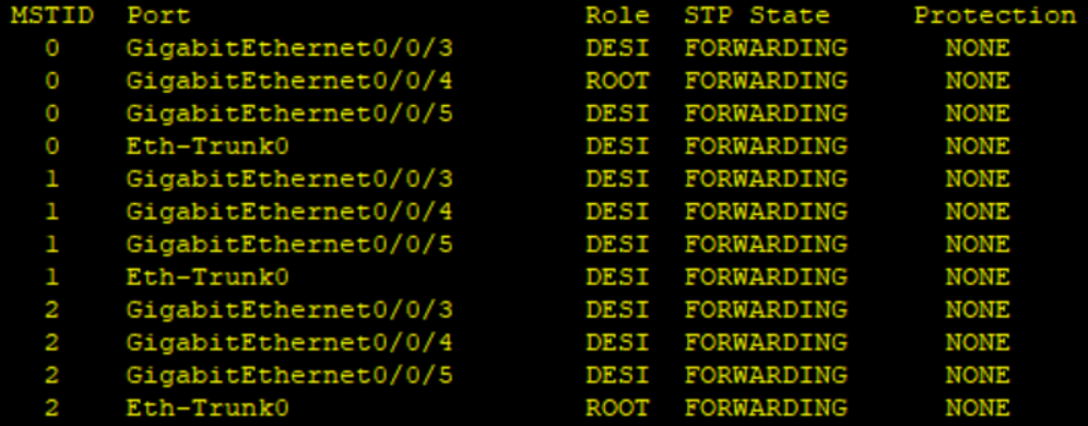
5.1查看生成树
1.sw1
2.sw2

3.sw3

4.sw4

5.2查看VRRP


5.3查看IP
1.R1

2.sw1

2.sw2

6.设备之间的连通性测试
pc1和pc2---pc1 ping pc2(vlan2 3)

内网访问外网

pc1和R1(广播域)
