蓝桥杯物联网竞赛_STM32L071_8_ADC扩展模块
原理图:
扩展模块原理图:
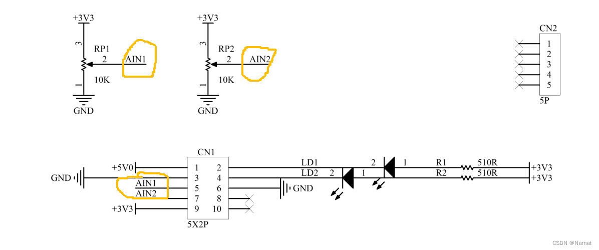
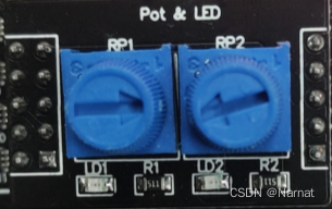
RP1和RP2分别对应着AIN1和AIN2,扭动它们,其对应滑动变阻器阻值也会变化
实验板接口原理图:

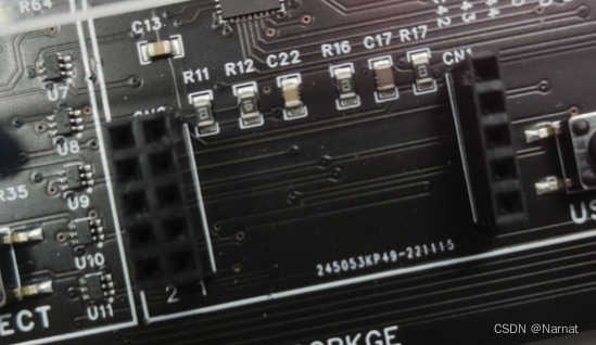
对应实验板接口PB1和PB0
即AN1对应PB1, AN2对应PB0
CubMx配置:
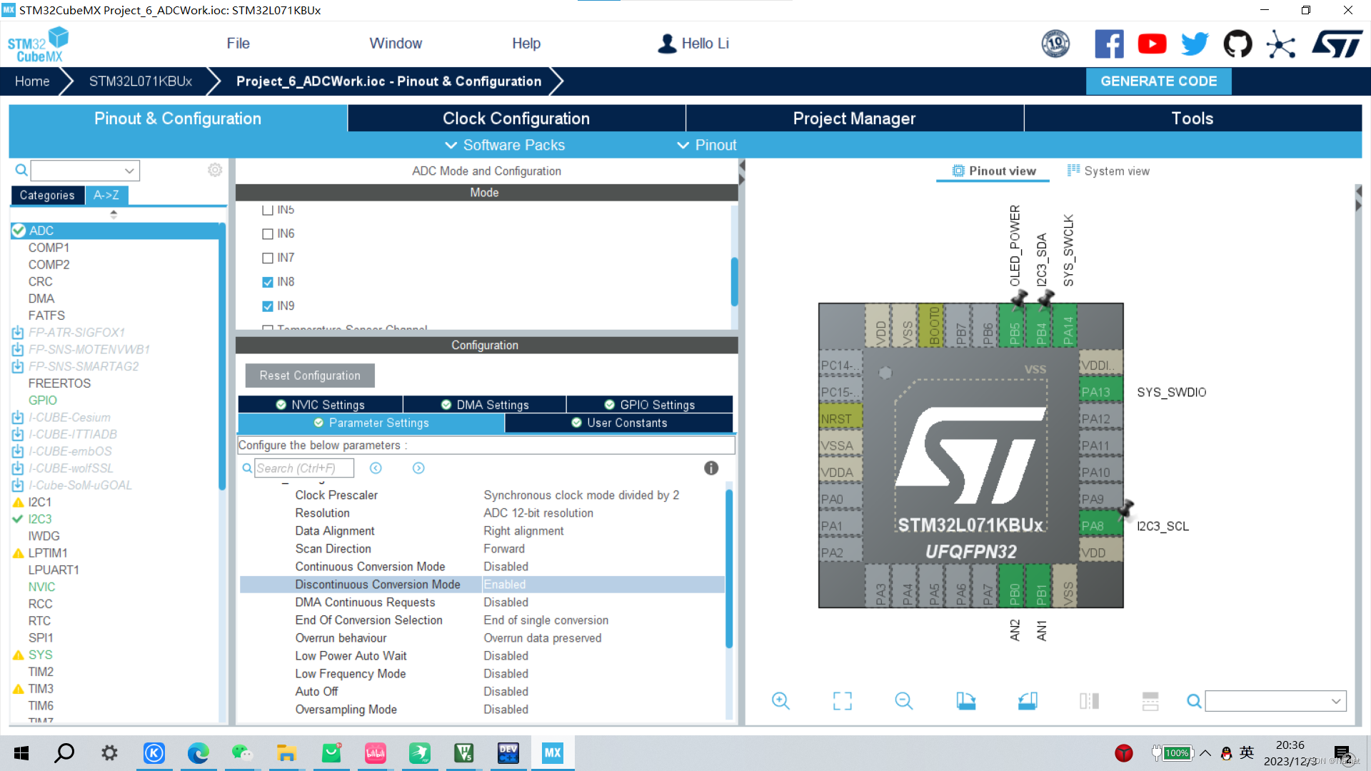
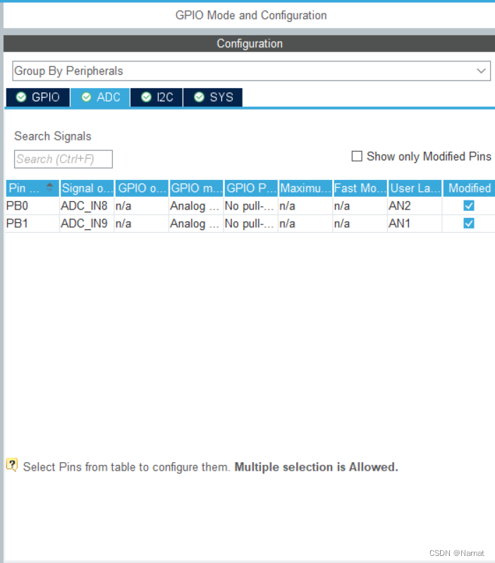
ADC通道IN8和IN9才对应PB0和PB1
keil配置:
Function:
#include "Function.h"
#include "i2c.h"
#include "oled.h"
#include <stdint.h>
#include "adc.h"

void OLED_Write(unsigned char type, unsigned char data){
	unsigned char Write_Data[2];
	Write_Data[0] = type;
	Write_Data[1] = data;
	HAL_I2C_Master_Transmit(&hi2c3, 0x78, Write_Data, 2, 0xff);
}

void Function_OledEnable(unsigned char ms){
	HAL_GPIO_WritePin(OLED_POWER_GPIO_Port, OLED_POWER_Pin, GPIO_PIN_RESET);
	HAL_Delay(ms);
	OLED_Init();
}

float* Function_GetAdc(unsigned char ms){
	uint16_t adc_data[2]; // 获取原始值
	static float adc_Value[3]; // 转化成浮点值

	for(unsigned char i = 0; i < 2; i ++){
		HAL_ADC_Start(&hadc); // 开启
		HAL_ADC_PollForConversion(&hadc, 0xff); // 等待ADC转换完成
		adc_data[i] = HAL_ADC_GetValue(&hadc);

		adc_Value[i] = ((float)adc_data[i]) * 3.30f/4095;

		HAL_Delay(ms); // 提高精度
	}
	HAL_ADC_Stop(&hadc); // 停止转换

	adc_Value[2] = adc_Value[1];
	adc_Value[1] = adc_Value[0];
	adc_Value[0] = adc_Value[2]; // 将0, 1的值调换一下

	return adc_Value;
}
#ifndef __FUNCTION__
#define __FUNCTION__

void OLED_Write(unsigned char type, unsigned char data);
void Function_OledEnable(unsigned char ms);
float* Function_GetAdc(unsigned char ms);
#endif
main:
#include "main.h"
#include "adc.h"
#include "i2c.h"
#include "gpio.h"
#include "Function.h"
#include "oled.h"

void SystemClock_Config(void);

int main(void)
{

	float * AdcGet;

  HAL_Init();


  SystemClock_Config();


  MX_GPIO_Init();
  MX_ADC_Init();
  MX_I2C3_Init();

  Function_OledEnable(50);

  while (1)
  {

    AdcGet = Function_GetAdc(10); // 获取ADC
		OLED_ShowNumber(0, 0, (uint32_t) (AdcGet[0] + 0.5), 2, 16);
		OLED_ShowNumber(0, 2, (uint32_t) (AdcGet[1] + 0.5), 2, 16);

  }

}


void SystemClock_Config(void)
{
  RCC_OscInitTypeDef RCC_OscInitStruct = {0};
  RCC_ClkInitTypeDef RCC_ClkInitStruct = {0};
  RCC_PeriphCLKInitTypeDef PeriphClkInit = {0};


  __HAL_PWR_VOLTAGESCALING_CONFIG(PWR_REGULATOR_VOLTAGE_SCALE1);


  RCC_OscInitStruct.OscillatorType = RCC_OSCILLATORTYPE_HSI;
  RCC_OscInitStruct.HSIState = RCC_HSI_ON;
  RCC_OscInitStruct.HSICalibrationValue = RCC_HSICALIBRATION_DEFAULT;
  RCC_OscInitStruct.PLL.PLLState = RCC_PLL_ON;
  RCC_OscInitStruct.PLL.PLLSource = RCC_PLLSOURCE_HSI;
  RCC_OscInitStruct.PLL.PLLMUL = RCC_PLLMUL_4;
  RCC_OscInitStruct.PLL.PLLDIV = RCC_PLLDIV_2;
  if (HAL_RCC_OscConfig(&RCC_OscInitStruct) != HAL_OK)
  {
    Error_Handler();
  }


  RCC_ClkInitStruct.ClockType = RCC_CLOCKTYPE_HCLK|RCC_CLOCKTYPE_SYSCLK
                              |RCC_CLOCKTYPE_PCLK1|RCC_CLOCKTYPE_PCLK2;
  RCC_ClkInitStruct.SYSCLKSource = RCC_SYSCLKSOURCE_PLLCLK;
  RCC_ClkInitStruct.AHBCLKDivider = RCC_SYSCLK_DIV1;
  RCC_ClkInitStruct.APB1CLKDivider = RCC_HCLK_DIV1;
  RCC_ClkInitStruct.APB2CLKDivider = RCC_HCLK_DIV1;

  if (HAL_RCC_ClockConfig(&RCC_ClkInitStruct, FLASH_LATENCY_1) != HAL_OK)
  {
    Error_Handler();
  }
  PeriphClkInit.PeriphClockSelection = RCC_PERIPHCLK_I2C3;
  PeriphClkInit.I2c3ClockSelection = RCC_I2C3CLKSOURCE_PCLK1;
  if (HAL_RCCEx_PeriphCLKConfig(&PeriphClkInit) != HAL_OK)
  {
    Error_Handler();
  }
}


void Error_Handler(void)
{

  __disable_irq();
  while (1)
  {
  }

}
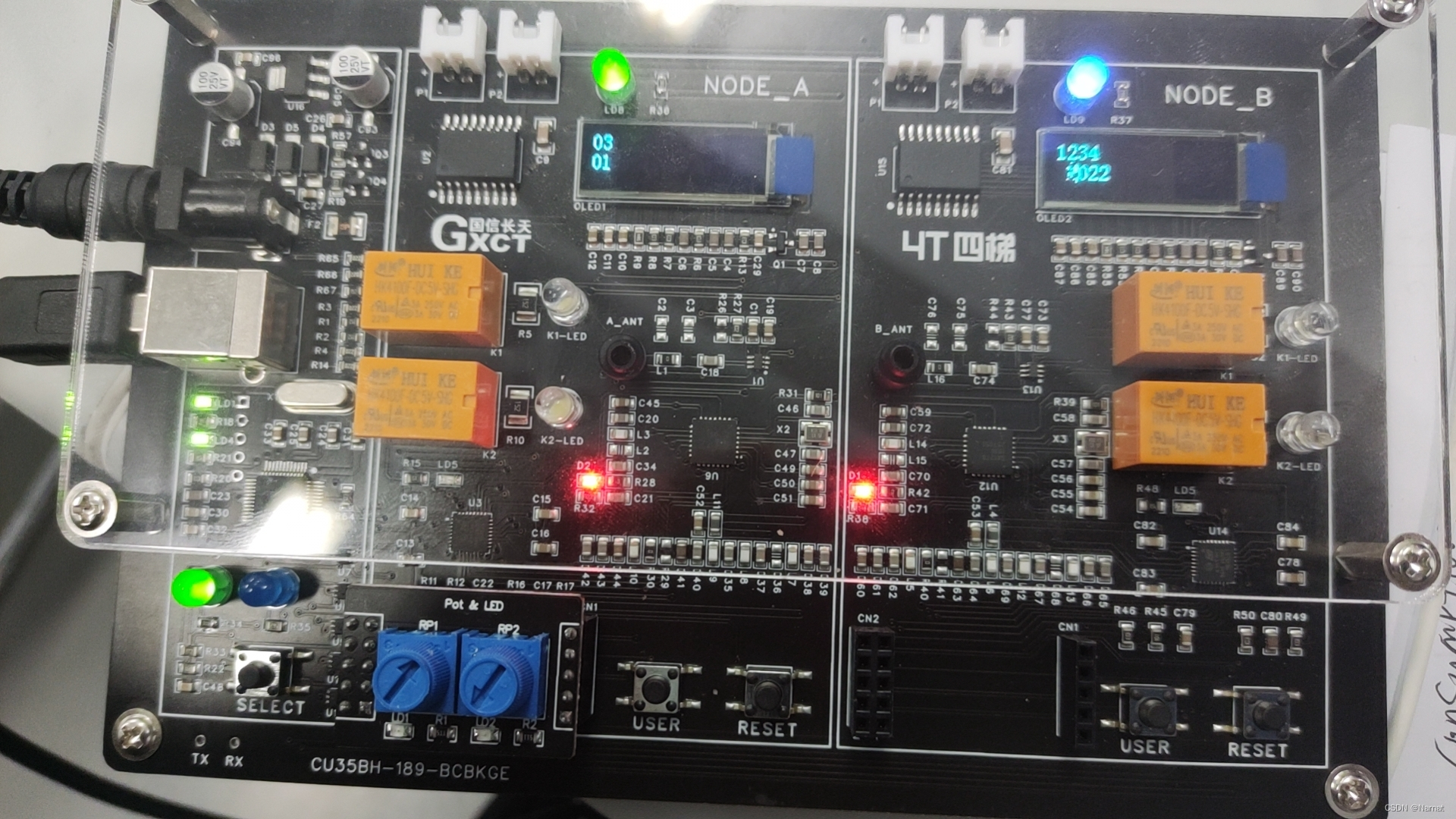
效果:
拓展:
Discontinuous Conversion Mode"是指在模数转换器(ADC)中的一种工作模式。在这种模式下,ADC只有在触发条件满足时才会进行转换,而不是连续地进行转换。
在"Discontinuous Conversion Mode"中,ADC会在每个触发事件(比如定时器溢出、外部触发等)发生时进行一次转换。这种模式适用于需要节省能量或者只在特定事件发生时才需要转换的应用场景。在这种模式下,ADC会在完成转换后自动进入低功耗模式,直到下一个触发事件发生。
这种模式的工作原理在不同的微控制器或者ADC芯片上可能会有所不同,因此具体的工作方式需要参考相应的数据手册或者技术文档。
3.3f表示数据为float类型单精度,3.3默认数据为double类型双精度
