verilog手撕代码3——序列检测和序列发生器
文章目录
- 前言
- 一、序列检测器
- 1.1 重复序列检测
- 1.1.1 序列缓存对比/移位寄存器法
- 1.1.2 状态机法
- 1.2 非重复序列检测
- 二、序列发生器
- 2.1 移位寄存器法
- 2.2 反馈法
- 2.3 计数器法
前言
2023.4.25
2023.4.26 学习打卡,天气转晴
一、序列检测器
1.1 重复序列检测
1.1.1 序列缓存对比/移位寄存器法
把输入的数据缓存到数组,然后与目标进行对比
例1:检测序列0111_0001,满足序列输出为1

module sequence_detect(
	input clk,
	input rst_n,
	input a,
	output reg match
	);

	reg [7:0] a_tem;

	always @(posedge clk or negedge rst_n)
		if (!rst_n)
			match <= 1'b0;
		else    //检测到目标序列的下一个周期输出高电平
			match <= (a_tem == 8'b0111_0001) ? 1'b1 : 1'b0;

	always @(posedge clk or negedge rst_n)
		if (!rst_n)
			a_tem <= 8'b0;
		else
			a_tem <= {a_tem[6:0],a};
endmodule
例2:检测序列1101,用移位寄存器实现

module detect_1101(
	input clk,
	input rst_n,
	input a,
	output data_out
);
	reg [3:0] a_r;

	always@(posedge clk or negedge rst_n)begin
		if(!rst_n)
			a_r <= 4'b0;
		else
			a_r <= {a_r[2:0], a};
	end

	assign data_out = a_r[3] & a_r[2] & ~a_r[1] & a_r[0];
endmodule
例3:含有无关项的序列检测
检测序列001_xxx_110,中间三位不关心,这种题目的话也可以是缓存序列对比
match <= (a_r[8:6]==3'b001 && a_r[2:0]==3'b110) ? 1 : 0;
例4:输入数据使能有效,不是所有输入数据都有效,检测0110序列
在data_valid=1的时候缓存数据,同理再进行比较(注意输出match为高电平的周期是什么时候,这里的match相当于和序列同时输出,只要满足就输出了)

module sequence_detect(
	input clk,
	input rst_n,
	input data,
	input data_valid,
	output reg match
	);

	reg [3:0] data_r;

	always @(posedge clk or negedge rst_n)begin
		if (!rst_n)
			data_r <= 4'b0;
		else
			data_r <= data_valid ? {data_r[2:0], data} : data_r;
	end

	always @(posedge clk or negedge rst_n)begin
		if (!rst_n)
			match <= 1'b0;
		else
			match <=  ({data_r[2:0], data}==4'b0110) ? 1 : 0;
	end
endmodule
1.1.2 状态机法
一般是三段式状态机
Moore型:输出信号只取决于当前状态;Mealy型:输出信号不仅取决于当前状态,还取决于输入;- 实现相同的功能时,Mealy型比Moore型能节省一个状态(大部分情况下能够节省一个触发器资源),Mealy型比Moore型输出超前一个时钟周期。
例1:用Moore型状态机实现序列“1101”从左至右的不重叠检测。

module det_moore(
   input                clk   ,
   input                rst_n ,
   input                din   ,

   output	reg         Y
);
    parameter idle=0,s0=1,s1=2,s2=3,s3=4;
    reg [2:0] state,nx;

    always@(posedge clk or negedge rst_n)begin
        if(!rst_n)
            state<=idle;
        else
            state<=nx;
    end

    always@(*)begin
        case(state)
            idle: nx=din?s0:idle;
            s0: nx=din?s1:idle;
            s1: nx=din?s1:s2;
            s2: nx=din?s3:idle;
            s3: nx=din?s0:idle;
            default: nx=idle;
        endcase
    end

    always@(posedge clk or negedge rst_n)begin
        if(!rst_n)
            Y <= 0;
        else
            Y <= (state==s3) ? 1 : 0;
    end
endmodule
1.2 非重复序列检测
例1:检测输入信号(a)是否满足011100序列, 要求以每六个输入为一组,不检测重复序列,例如第一位数据不符合,则不考虑后五位。一直到第七位数据即下一组信号的第一位开始检测。当信号满足该序列,给出指示信号match。当不满足时给出指示信号not_match。(每六个数为一组进行检查)
分析:和移位寄存器有所不同,这种是缓存六个数据比较后,要清空所有的数据,然后再次缓存新的六个数据比较,所以需要用到计数器。
match和not_match仅在cnt==5时才进行更新,且nm状态在cnt == 5以及data==0的时候才会跳转到新的有效状态,否则一直都会是nm。

module sequence_detect(
	input clk,
	input rst_n,
	input data,
	output reg match,
	output reg not_match
	);

	reg [2:0] state,nx;
	reg [2:0] cnt;
	parameter s0=0,s1=1,s2=2,s3=3,s4=4,s5=5,s6=6,nm=7;

	always@(posedge clk or negedge rst_n)begin
		if(!rst_n)begin
			cnt<=0;
		end
		else if(cnt==5)
			cnt<=0;
		else
			cnt<=cnt+1;
	end


	always@(posedge clk or negedge rst_n)begin
		if(!rst_n)begin
			state<=0;
		end
		else
			state<=nx;
	end

	always@(*)begin
		case(state)
			s0:nx<=data?nm:s1;
			s1:nx<=data?s2:nm;
			s2:nx<=data?s3:nm;
			s3:nx<=data?s4:nm;
			s4:nx<=data?nm:s5;
			s5:nx<=data?nm:s6;
			s6:nx<=data?s0:nm;
			nm:nx<=(cnt==5 && data==0)?s1:nm;  //只有同时满足两个条件才会跳转,否则一直是nm
			default:nx<=s0;
		endcase
	end

	always@(posedge clk or negedge rst_n)begin
		if(!rst_n)begin
			match<=0;
			not_match<=0;
		end
		else if(cnt==5)begin
			if(nx==s6)begin
				match<=1;
				not_match<=0;
			end
			else begin
				match<=0;
				not_match<=1;
			end
		end
		else begin
			match<=0;
			not_match<=0;
		end
	end
endmodule
二、序列发生器
2.1 移位寄存器法
例1:循环输出序列001011
module sequence_generator(
	input clk,
	input rst_n,
	output reg data
	);

    reg [5:0] q;

    always@(posedge clk or negedge rst_n)
        if (!rst_n)
            q <= 6'b001011;
        else
            q <= {q[4:0],q[5]};  //序列左移

    always@(posedge clk or negedge rst_n)
        if (!rst_n)
            data <= 1'd0;
        else
            data <= q[5];
endmodule
2.2 反馈法
由移位寄存器和组合逻辑生成,也是寄存器的某一位输出端输出循环序列,但是使用到的寄存器数目减少了。
- 根据给定序列信号的循环周期M,确定移位寄存器位数n,2^ (n-1) < M ≤ 2^n。如果发现序列中有状态重复的话,就把n加一。
- 根据M个不同的状态列出移位寄存器的态序表和反馈函数表,求出反馈函数F的表达式。
- 各个寄存器的输出需要经过反馈网络,然后才连接到移位寄存器的输入端
- 检查自启动:电路能从无效状态进入有效状态
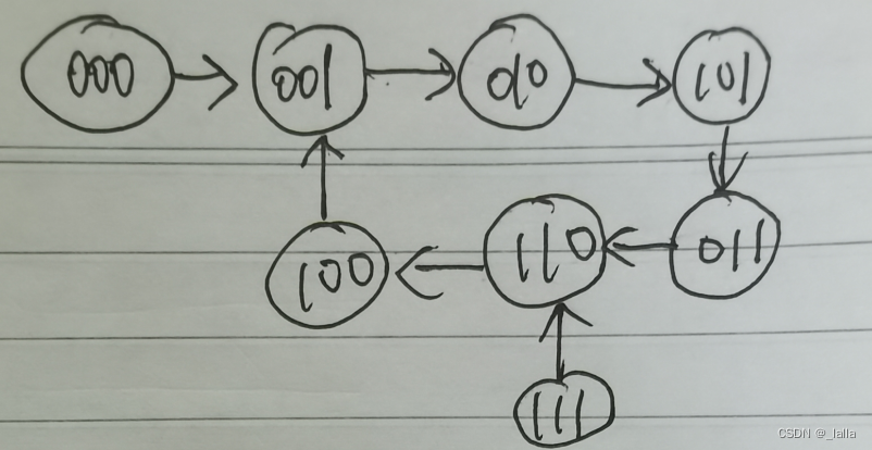
序列001011:至少需要3位,列出状态,001-010-101-011-110-100,可以看到寄存器高位Q2输出的数据就是我们想要的序列。
| Q2 | Q1 | Q0 | F |
|---|---|---|---|
| 0 | 0 | 1 | 0 |
| 0 | 1 | 0 | 1 |
| 1 | 0 | 1 | 1 |
| 0 | 1 | 1 | 0 |
| 1 | 1 | 0 | 0 |
| 1 | 0 | 0 | 1 |
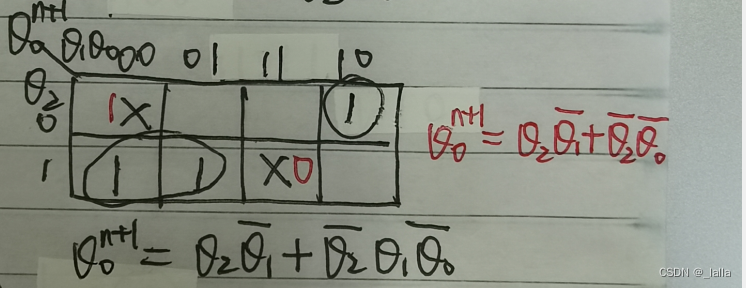
根据上面的反馈函数表,画出卡诺图,可以写出F的表达式如下。然后把这些组合逻辑接到Q0的输入端即可。

F = Q2 & ~Q1 | ~Q2 & Q1 & ~Q0;
可以看到,上面000和111的状态是无关项,可以把其设置为1和0,这样F的表达式可以进一步化简。同时画出状态转移图,是可以自启动的。
F = Q2 & ~Q1 | ~Q2 & ~Q0;

module generate_001110(
	input clk,
	input rst_n,
	input [2:0] D,
	output q
	);

	reg [2:0] q_r;
	wire Din;

	always@(posedge clk or negedge rst_n)begin
		if(!rst_n)
			q_r <= D;
		else
			q_r <= {q_r[1:0], Din};
	end

	assign q = q_r[2];
	assign Din = q_r[2] & ~q_r[1] | ~q_r[2] & ~q_r[0];
endmodule
2.3 计数器法
产生序列:001110,计数器范围为0-5,分别对应输出序列各个值。
由卡诺图化简可以得到Z的最简表达式。
| Q2 | Q1 | Q0 | Z |
|---|---|---|---|
| 0 | 0 | 0 | 0 |
| 0 | 0 | 1 | 0 |
| 0 | 1 | 0 | 1 |
| 0 | 1 | 1 | 1 |
| 1 | 0 | 0 | 1 |
| 1 | 0 | 1 | 0 |
module seq_gen_count(
    input clk,
    input rst_n,
    output seq
    );

	reg [2:0]count;
	always@(posedge clk or negedge rst_n)begin
	    if(!rst_n)
	        count <= 0;
	    else
	        count <= (count == 5) ? 0 : count + 1;
	end

	assign seq = (!count[2] & count[1]) | (count[2] & !count[1] & !count[0]);
endmodule
