S32K312 RTD 4.0.0 版本 OCU 例程配置流程说明
一、前言
由于 RTD 4.0.0 版本并没有 S32K312 相关例程,本文基于已有的 S32K344 OCU 例程,新建 S32K312 工程,讲解 OCU 例程的相关配置流程。
二、基本概念
- OCU(Output Compare Unit – 输出比较单元)本质上是一个计数器,计数器逐一累加直到达到预设值,达到预设值后计数器会清零,重新开始累加,循环往复。
- OCU 配置需要一个绑定到一个可用硬件通道的逻辑通道,当比较匹配发生(即计数器达到预设值)时,会触发一个硬件中断和一个输出引脚的状态改变(电平翻转)。
- OCU 逻辑通道包含计数器预设值的定义,最大计数器值(一般为 65535),通知回调到用户定义的函数、硬件通道指定引脚的行为和预分频器值(可选第二个预分频器)的设置,如下图 1 所示:
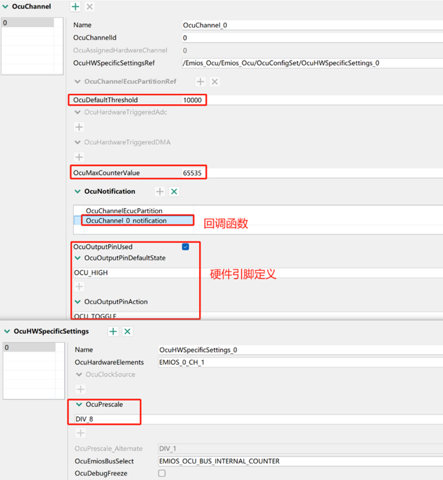
图 1 OCU 逻辑通道配置
三、OCU 配置流程
- OCU 配置需要一个绑定到一个可用硬件通道的逻辑通道,当比较匹配发生(即计数器达到预设值)时,会触发一个硬件中断和一个输出引脚的状态改变(电平翻转),这里使能 PTB13 为 OCU 的输出引脚(配置为 eMIOS、输出),使能 PTA29 为输出 GPIO(控制红灯亮灭)。
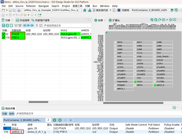
图 2 PTA29 & PTB13 管脚配置
- 添加如图 3 所示外设模块,并配置 Emios_Ocu、Emios_Mcu_Ip 及 IntCtrl_Ip 模块。
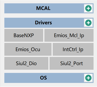
图 3 具体驱动模块
a. Emios_Ocu 模块配置
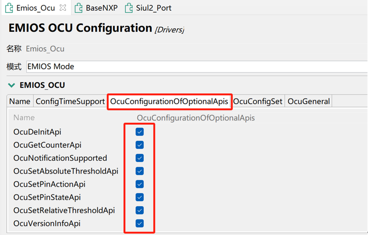
图 4 使能 OCU API 函数功能
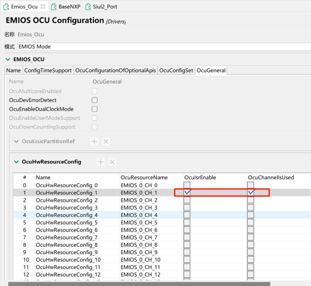
图 5 使能 EMIOS0_CH1 对应 OCU 功能
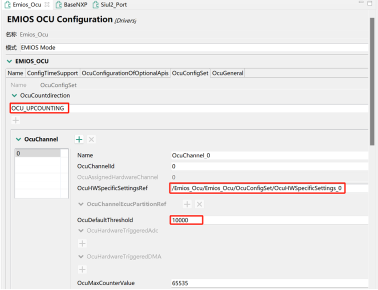
图 6 设置 OCU 计数方式及计数阈值
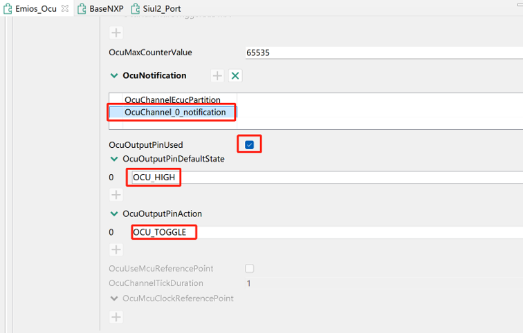
图 7 OCU 通知函数及输出引脚状态变化配置
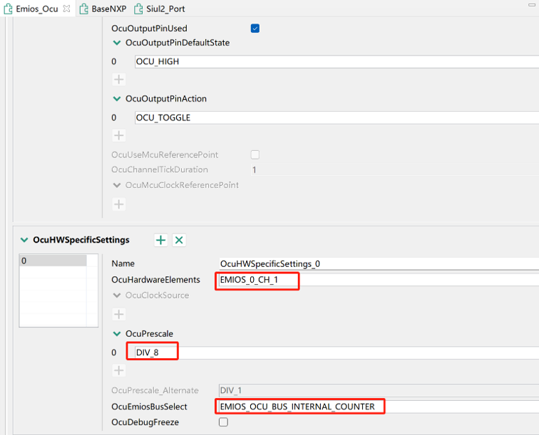
图 8 设置 OCU 关联硬件中断通道及预分频值
b. Emios_Mcl_Ip 模块配置
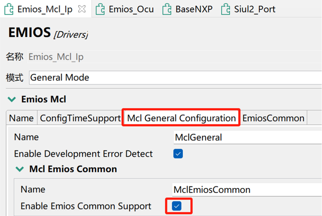
图 9 使能 EMIOS 通用功能
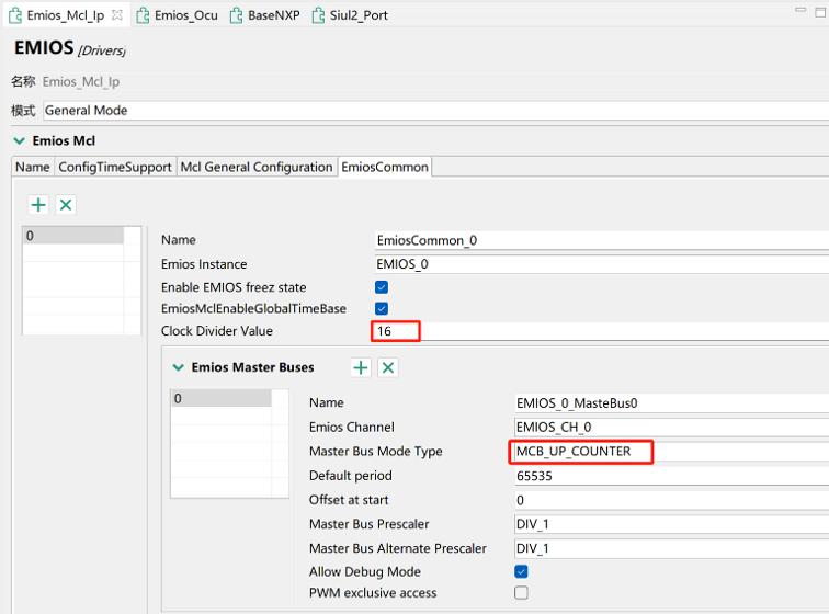
图 10 设置时钟分频及计数模式
c. IntCtrl_Ip 模块配置:查看图 11,可知 EMIOS0_CH1 对应中断服务函数为 EMIOS0_5_IRQ,具体配置如图 12 所示。
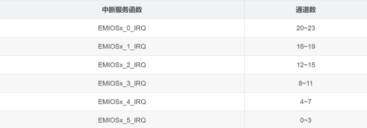
图 11 EMIOS 通道对应的中断服务函数
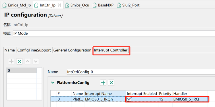
图 12 使能 EMIOS0_CH1 对应中断服务函数
- main.c 函数
#include "Emios_Ocu_Ip.h"
#include "Emios_Mcl_Ip.h"
#include "Emios_Mcl_Ip_Irq.h"
#include "Clock_Ip.h"
#include "IntCtrl_Ip.h"
#include "Siul2_Port_Ip.h"
#include "Siul2_Dio_Ip.h"

#define clockConfig &Clock_Ip_aClockConfig[0]
#define EMIOS_0       (0U)
#define CHANNEL_1     (1U)
/* Global flag updated in irq */
static volatile uint8 toggleLed = 0U;

void OcuChannel_0_notification(void);
/**
* @brief    Emios notification periodically called by the configured channel
* @details  Used to blink a led
*/
void OcuChannel_0_notification(void)
{
    static uint16 count = 0U;

    if (++count >= 10U)
    {
        toggleLed = 1U;
        count = 0;
    }
}
/**
* @brief        Main function of the example
* @details      Initialize the used drivers and uses the Ocu
*               and Siul2_Dio drivers to toggle a LED periodically
*/

int main(void)
{
    uint8 stateLed = 0;

    /* Initialize clock */
    Clock_Ip_Init(clockConfig);

    /* Initialize all pins using the Siul2_Port driver */
    Siul2_Port_Ip_Init(NUM_OF_CONFIGURED_PINS_PortContainer_0_BOARD_InitPeripherals, g_pin_mux_InitConfigArr_PortContainer_0_BOARD_InitPeripherals);

    /* Set eMios interrupt */
    IntCtrl_Ip_Init(&IntCtrlConfig_0);
    IntCtrl_Ip_EnableIrq(0U);

    /* Initialize eMios_Mcl for enable global counter bus */
    Emios_Mcl_Ip_Init(EMIOS_0, &Emios_Mcl_Ip_0_Config_BOARD_INITPERIPHERALS);

    /* Initialize eMios_Ocu */
    Emios_Ocu_Ip_Init(&Emios_Ocu_Ip_0_ModuleCfgPB);

    /* Enable eMios_Ocu channel notification */
    Emios_Ocu_Ip_EnableNotification(EMIOS_0,CHANNEL_1);

    /* Start eMios_Ocu Channel */
    Emios_Ocu_Ip_StartChannel(EMIOS_0,CHANNEL_1);

    while (1)
    {
        /* Toggle the LED when the Ocu notification is called */
        if (1U == toggleLed)
        {
            toggleLed = 0;
            Siul2_Dio_Ip_WritePin(LED_RED_PORT, LED_RED_PIN, stateLed);
            stateLed = stateLed ^ 1U;
        }
    }
}- 完成工程的编译和烧录之后,原厂 S32K312 开发板红灯会持续 1s 亮一次,具体如下图所示:
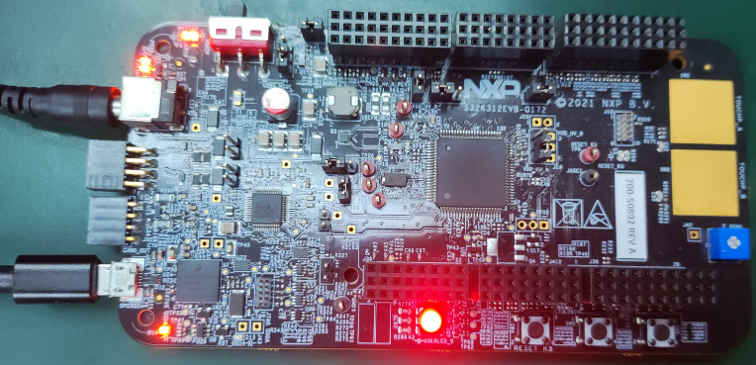
图 13 硬件现象
四、总结
参照上述【OCU 配置流程】的步骤 1、2、3 完成管脚使能、相关外设模块的添加与配置以及 main.c 源程序的复制与修改,即可完成 OCU 例程配置,感谢您阅读本文!
五、参考文献
[1] RTD_OCU_UM.pdf
[2] S32K3XXRM Rev7.pdf
欢迎登录大大通,阅读原文,浏览更多精彩技术内容吧!
