网络系统集成实验(三)| 系统集成虚拟局域网(VLAN)配置
目录
一、前言
二、实验目的
三、实验需求
四、实验步骤与现象
Step1:需求分析及配置思路
Step2:实验拓扑设计
Step3:实验配置
Part1:公网IP配置
Part2:链路聚合
Part3:VLAN的创建与划分
Part4:RSTP相关配置
Part5:VRRP相关配置
Part6:DHCP相关配置
Part7: IP补充配置
Part8:NAT配置
Part9:OSPF配置
Part10:ACL配置
Part11:Telnet配置
Step4:效果验证
① 链路聚合
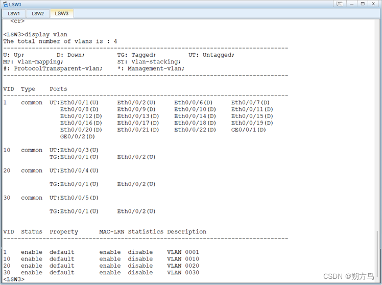
② VLAN的划分
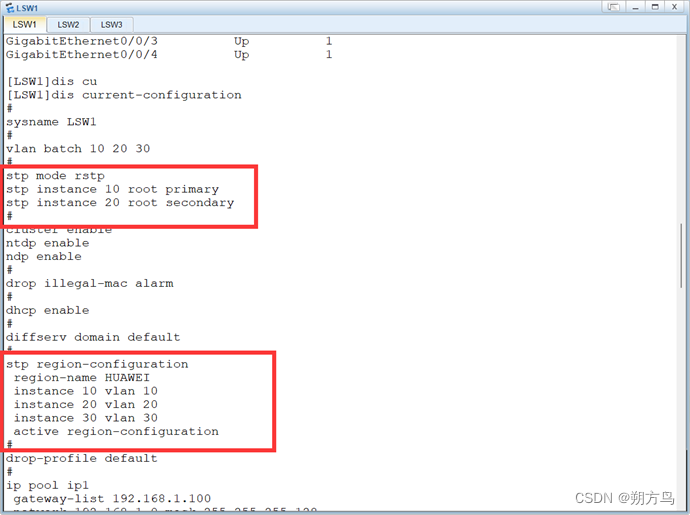
③ RSTP配置
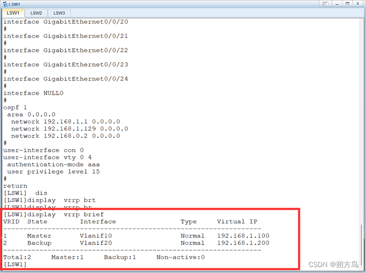
④ VRRP效果
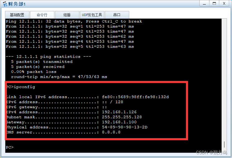
⑤ DHCP效果
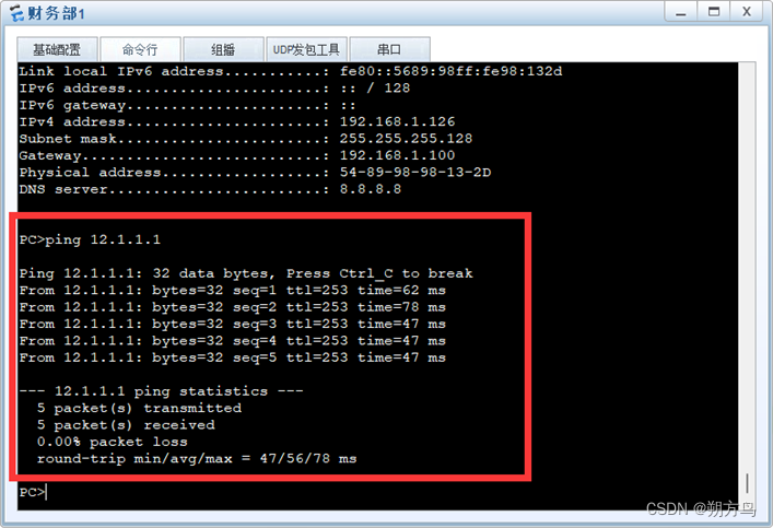
⑥ NAT效果
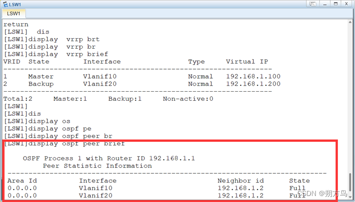
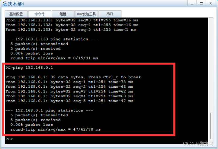
⑦ OSPF邻居建立及全网互通
⑧ 财务部服务器限制访问
⑨ Telnet效果
一、前言
该系列文章将会对网络系统集成课程中相关实验进行更新,本篇为第三篇(网络虚拟局域网配置),该篇比较综合,包括了NAT配置、VLAN划分、Telnet等各类技术。
另:
该文章所搭建的拓扑将会成为接下来的实验的基本文件,请重点关注。
该文章所搭建的拓扑将会成为接下来的实验的基本文件,请重点关注。
该文章所搭建的拓扑将会成为接下来的实验的基本文件,请重点关注。
二、实验目的
① 掌握网段的划分技巧
② 掌握NAT的配置方法
③ 学习华为设备的Telnet配置方法
④ 掌握常见的冗余配置方法
⑤ 学习VLAN的划分以及限制
三、实验需求
① 进行网络需求分析
② 进行网络拓扑规划
③ 在ENSP中实现该规划并形成.topo文件
四、实验步骤与现象
Step1:需求分析及配置思路
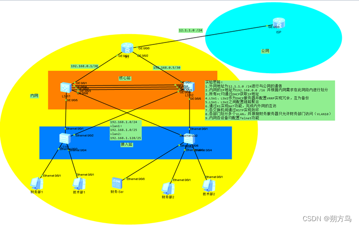
① 外网地址为12.1.1.0 /24进行与公网的通信
② 内网的IP地址为192.168.0.0 /16 并根据内网需求在此网段内进行划分
③ 所有PC均通过DHCP获取IP地址
④ LSW1、LSW2作为DHCP服务器并配置VRRP实现冗余,互为备份
⑤ LSW1、LSW2之间配置链路聚合
⑥ 通过R1实现NAT功能,完成内外网的互访
⑦ 各交换机间通过RSTP实现防环
⑧ 各部门划分多个VLAN,并限制财务服务器只允许财务部门访问
⑨ 内网各设备均配置Telnet功能
Step2:实验拓扑设计
实验拓扑图如下:
Step3:实验配置
Part1:公网IP配置
① R1:
1.	#
2.	interface GigabitEthernet0/0/0
3.	 ip address 12.1.1.2 255.255.255.0
4.	#
② ISP:
1.	#
2.	interface GigabitEthernet0/0/0
3.	 ip address 12.1.1.1 255.255.255.0
4.	#
Part2:链路聚合
① LSW1:
1.	#
2.	interface Eth-Trunk1
3.	#
4.	interface GigabitEthernet0/0/2
5.	 eth-trunk 1
6.	#
7.	interface GigabitEthernet0/0/3
8.	 eth-trunk 1
9.	#
10.	interface GigabitEthernet0/0/4
11.	 eth-trunk 1
12.	#
② LSW2:
1.	#
2.	interface Eth-Trunk1
3.	#
4.	interface GigabitEthernet0/0/2
5.	 eth-trunk 1
6.	#
7.	interface GigabitEthernet0/0/3
8.	 eth-trunk 1
9.	#
10.	interface GigabitEthernet0/0/4
11.	 eth-trunk 1
12.	#
Part3:VLAN的创建与划分
① 在所有的交换机上都创建VLAN10、VLAN20
1.	vlan batch 10 20
2.	#
② 在LSW3、LSW4与PC的接口上划分相应的VLAN
1.	#
2.	interface Ethernet0/0/3
3.	 port link-type access
4.	 port default vlan 10
5.	#
6.	interface Ethernet0/0/4
7.	 port link-type access
8.	 port default vlan 20
9.	#
另 LSW4:
1.	#
2.	interface Ethernet0/0/6
3.	 port link-type access
4.	 port default vlan 10
5.	#
③ LSW1、LSW2、LSW3、LSW4的互联接口配置为Trunk接口
LSW1及LSW2:
1.	#
2.	interface Eth-Trunk1
3.	 port link-type trunk
4.	 port trunk allow-pass vlan 2 to 4094
5.	#
6.	interface GigabitEthernet0/0/5
7.	 port link-type trunk
8.	 port trunk allow-pass vlan 2 to 4094
9.	#
10.	interface GigabitEthernet0/0/6
11.	 port link-type trunk
12.	 port trunk allow-pass vlan 2 to 4094
13.	#
LSW3及LSW4:
1.	#
2.	interface Ethernet0/0/1
3.	 port link-type trunk
4.	 port trunk allow-pass vlan 2 to 4094
5.	#
6.	interface Ethernet0/0/2
7.	 port link-type trunk
8.	 port trunk allow-pass vlan 2 to 4094
9.	#
Part4:RSTP相关配置
在LSW1-LSW4上配置如下:
1.	#
2.	stp mode rstp
3.	#
4.	stp region-configuration
5.	 region-name HUAWEI
6.	 instance 10 vlan 10
7.	 instance 20 vlan 20
8.	 active region-configuration
9.	#
此外,为了减少BPDU的发送量、降低网络流量消耗,对于LSW1-LSW4的非互联接口配置边缘端口,其配置如下:
LSW1及LSW2:
1.	#
2.	interface GigabitEthernet0/0/1
3.	 stp edged-port enable
4.	#
LSW3及LSW4:
1.	#
2.	interface Ethernet0/0/3
3.	 port link-type access
4.	 port default vlan 10
5.	 stp edged-port enable
6.	#
7.	interface Ethernet0/0/4
8.	 port link-type access
9.	 port default vlan 20
10.	 stp edged-port enable
11. # 此外,在instance10中,将LSW1作为根桥,在instance 20 中,将LSW2作为根桥,配置如下:
LSW1:
1.	#
2.	stp mode rstp
3.	stp instance 10 root primary
4.	stp instance 20 root secondary
5.	#
LSW2:
1.	#
2.	stp mode rstp
3.	stp instance 20 root primary
4.	stp instance 10 root secondary
5.	#
Part5:VRRP相关配置
① 基础SVI配置:
LSW1:
1.	#
2.	interface Vlanif10
3.	 ip address 192.168.1.1 255.255.255.128
4.	#
5.	interface Vlanif20
6.	 ip address 192.168.1.129 255.255.255.128
7.	#
LSW2:
1.	#
2.	interface Vlanif10
3.	 ip address 192.168.1.2 255.255.255.128
4.	#
5.	interface Vlanif20
6.	 ip address 192.168.1.130 255.255.255.128
7.	#
② VRRP配置
LSW1:
1.	#
2.	interface Vlanif10
3.	 ip address 192.168.1.1 255.255.255.128
4.	 vrrp vrid 1 virtual-ip 192.168.1.100
5.	 vrrp vrid 1 priority 200
6.	 vrrp vrid 1 preempt-mode timer delay 60
7.	#
8.	interface Vlanif20
9.	 ip address 192.168.1.129 255.255.255.128
10.	 vrrp vrid 2 virtual-ip 192.168.1.200
11.	 vrrp vrid 2 preempt-mode timer delay 60
12.	#
LSW2:
1.	#
2.	interface Vlanif10
3.	 ip address 192.168.1.1 255.255.255.128
4.	 vrrp vrid 1 virtual-ip 192.168.1.100
5.	 vrrp vrid 1 preempt-mode timer delay 60
6.	#
7.	interface Vlanif20
8.	 ip address 192.168.1.129 255.255.255.128
9.	 vrrp vrid 2 virtual-ip 192.168.1.200
10.	 vrrp vrid 2 preempt-mode timer delay 60
11.	 vrrp vrid 2 priority 200
12.	#
Part6:DHCP相关配置
LSW1及LSW2:
1.	#
2.	ip pool ip1
3.	 gateway-list 192.168.1.100
4.	 network 192.168.1.0 mask 255.255.255.128
5.	 dns-list 8.8.8.8
6.	#
7.	ip pool ip2
8.	 gateway-list 192.168.1.200
9.	 network 192.168.1.128 mask 255.255.255.128
10.	 dns-list 8.8.8.8
11.	#
12.	#
13.	interface Vlanif10
14.	 dhcp select global
15.	#
16.	interface Vlanif20
17.	 dhcp select global
18.	#
Part7: IP补充配置
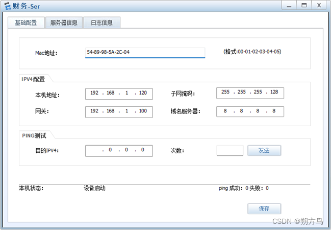
财务服务器IP配置如下:
LSW1及LSW2的IP补充配置如下:
LSW1:
1.	#
2.	interface Vlanif30
3.	 ip address 192.168.0.2 255.255.255.252
4.	#
5.	#
6.	interface GigabitEthernet0/0/1
7.	 port link-type access
8.	 port default vlan 30
9.	 stp edged-port enable
10.	#
LSW2:
1.	#
2.	interface Vlanif30
3.	ip address 192.168.0.6 255.255.255.252
4.	#
5.	#
6.	interface GigabitEthernet0/0/1
7.	port link-type access
8.	port default vlan 30
9.	stp edged-port enable
10.	#
Part8:NAT配置
考虑到NAT的配置复杂度,采取Easy-ip的配置方案,在R1上配置如下:
1.	#
2.	acl number 2000
3.	 rule 5 permit source 192.168.0.0 0.0.255.255
4.	 rule 10 deny
5.	#
6.	#
7.	 nat alg dns enable
8.	 nat alg ftp enable
9.	 nat alg rtsp enable
10.	 nat alg sip enable
11.	 #
12.	 nat address-group 1 12.1.1.5 12.1.1.200
13.	#
14.	#
15.	interface GigabitEthernet0/0/0
16.	 ip address 12.1.1.2 255.255.255.0
17.	 nat outbound 2000 address-group 1
18.	#
19.	ip route-static 0.0.0.0 0.0.0.0 12.1.1.1
20.
Part9:OSPF配置
为了保证网络之间的各设备能够正常通信,配置OSPF实现,各设备配置如下:
R1:
1.	#
2.	ospf 1
3.	#
4.	 area 0.0.0.0
5.	  network 12.1.1.2 0.0.0.0
6.	  network 192.168.0.1 0.0.0.0
7.	  network 192.168.0.5 0.0.0.0
8.	#
LSW1:
1.	#
2.	ospf 1
3.	#
4.	 area 0.0.0.0
5.	  network 192.168.1.1 0.0.0.0
6.	  network 192.168.1.129 0.0.0.0
7.	  network 192.168.0.2 0.0.0.0
8.	#
LSW2:
1.	#
2.	ospf 1
3.	#
4.	 area 0.0.0.0
5.	  network 192.168.1.2 0.0.0.0
6.	  network 192.168.1.130 0.0.0.0
7.	  network 192.168.0.6 0.0.0.0
Part10:ACL配置
为了保证仅允许财务部门访问财务服务器,配置ACL实现,在LSW4上配置如下:
1.	#
2.	acl number 2000
3.	 rule 5 permit source 192.168.1.0 0.0.0.127
4.	 rule 10 deny
5.	#
6.	#
7.	interface Ethernet0/0/6
8.	 port link-type access
9.	 port default vlan 10
10.	 traffic-filter outbound acl 2000
11.	#
Part11:Telnet配置
① 缺失IP配置
由于LSW3和LSW4并没有配置IP地址,因此需要首先给这两台设备配置IP地址,可以借助已经划分好VLAN的接口,直接在Vlanif中配置IP地址
LSW3:
1.	#
2.	interface Vlanif10
3.	 ip address 192.168.1.33 255.255.255.128
4.	#
5.	interface Vlanif20
6.	 ip address 192.168.1.133 255.255.255.128
7.	#
LSW4:
1.	#
2.	interface Vlanif10
3.	 ip address 192.168.1.44 255.255.255.128
4.	#
5.	interface Vlanif20
6.	 ip address 192.168.1.144 255.255.255.128
7.	#
② Telnet配置
交换机采用AAA认证,各设备的配置基本一致,配置命令如下:
1.	user-interface vty 0 4
2.	authentication-mode aaa
3.	user privilege level 15
4.	aaa
5.	local-user huawei password cipher huawei123
6.	local-user huawei privilege level 15
7.	local-user huawei service-type telnet
R1使用密码认证,配置命令如下:
1.	user-interface vty 0 4
2.	 authentication-mode password
3.	Please configure the login password (maximum length 16):SFN
Step4:效果验证
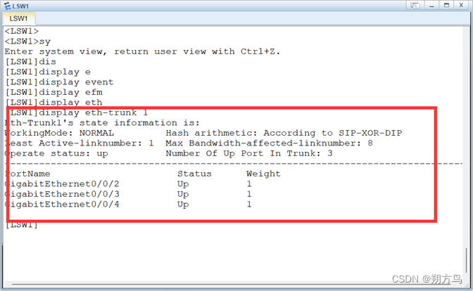
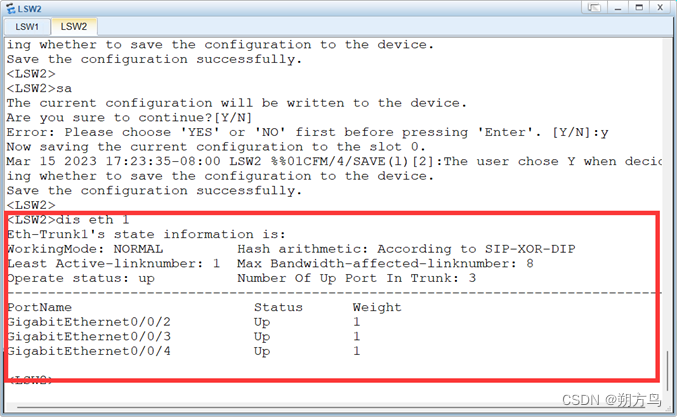
① 链路聚合
在LSW1及LSW2中查看如下:
② VLAN的划分
以LSW3为例,查看VLAN是否划分正确:
③ RSTP配置
RSTP配置难以验证,在此对于相关指令进行查看,以LSW1为例:
④ VRRP效果
以LSW1为例,查看是否形成网关冗余:
⑤ DHCP效果
以财务部1为例,查看是否获取到IP地址:
⑥ NAT效果
以财务部1为例,查看能否访问公网IP 12.1.1.1,效果如下:
⑦ OSPF邻居建立及全网互通
以LSW1为例,查看其OSPF邻居关系如下:
以技术部1为例,验证能否正常访问R1:
⑧ 财务部服务器限制访问
以财务部1为例,验证能否访问财务部服务器:
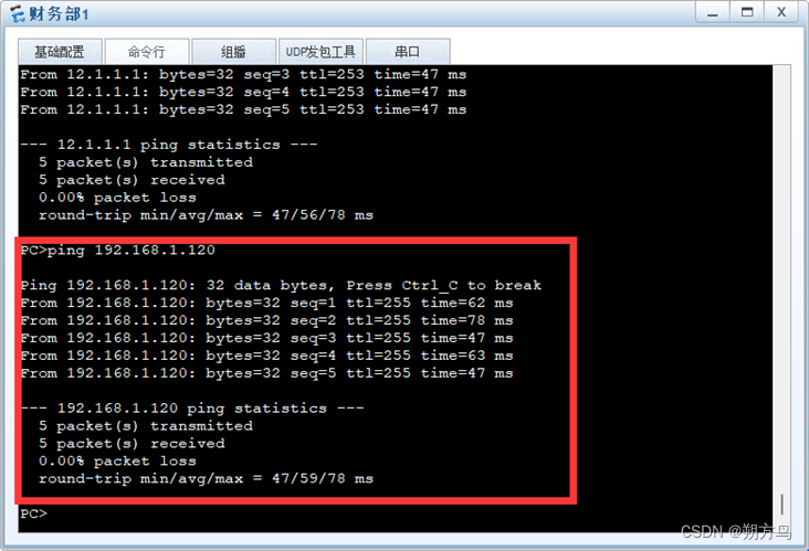
财务部门访问正常。
以技术部1为例,验证能否访问财务部服务器:
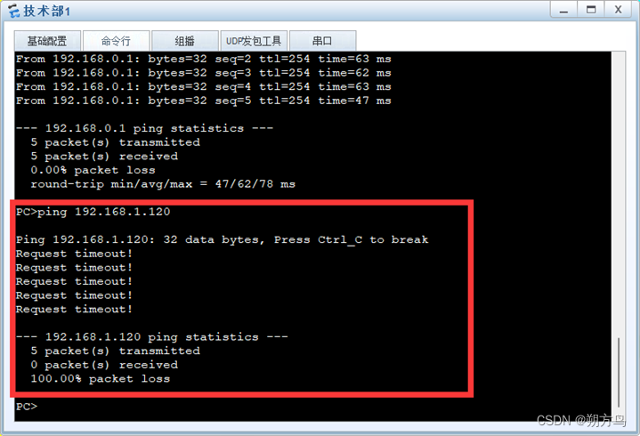
技术部门无法正常访问财务部服务器。
⑨ Telnet效果
以R1为例,验证能否正常Telnet
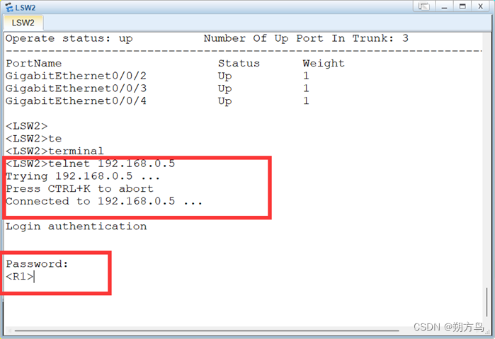
Telnet能够正常访问。
以LSW1为例,验证能否正常Telnet:
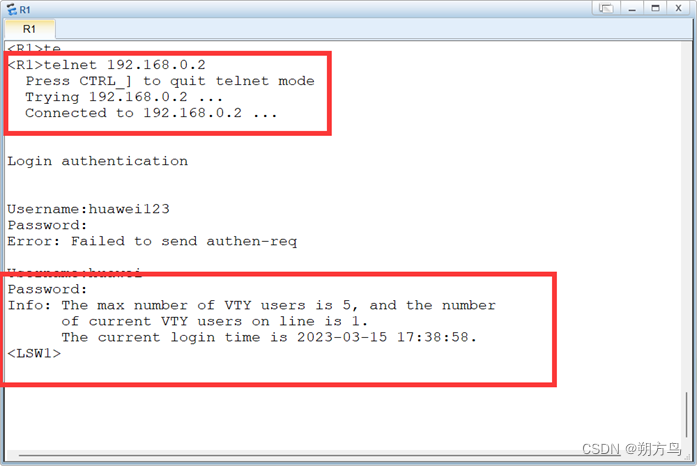
Telnet能够正常访问。
